Configuration
6.1 Basic knowledge for configuring
SIVACON 8PS - Configuring with LX system
94
Configuration Manual, 10/2011, A5E02194899-02
6.1.3.5
Connection to Siemens power distribution systems
Versions
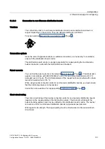
The electrical connection to the SIVACON system is carried out using special busbar
connection units. Enclosure connection is via the associated distribution board flanges. The
distribution board flanges are included in the scope of supply of the busbar connection units
and are secured in the standard cutout in the ceiling or base plate in the SIVACON. This
ensures the suitable insertion opening in each case for the assigned busbar system.
Connection options
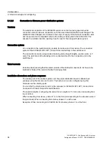
LX connection to the switchboard is possible from above and from below. The connection
system of the SIVACON 8PV, 8PT, S4 and S8 is located fully in the switchboard.
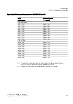
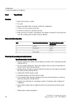
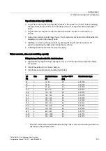
The connection is made using standard trunking units, straight lengths, junction units, or T
units. The joint block of the trunking unit is connected direct to the connection unit in the
switchboard.
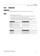
Rated currents
Consider when planning that the rated currents of the distribution boards do not have to be
identical to those of the selected busbar trunking system.
Installation dimensions and phase sequence
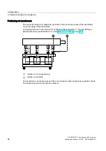
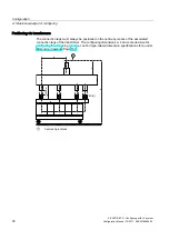
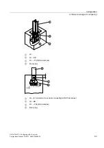
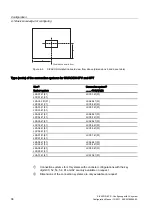
The centre point of the busbar system over the power distribution board is determined
precisely using the dimensions b and d. The busbar run can be configured using this
dimension as the starting point.
You can find the dimensions b and d in the manuals for SIVACON 8PV, 8PT, S4 and S8 or
on request in Product Support for switchboards.
The insertion depths (configuring dimension for run length) is 112 mm when connecting from
top or bottom.
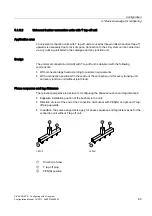
When connecting from above, phase L1 is to the front (corresponding to the actuation side of
the joint block). When connecting from below, phase L1 is at the rear.
Exception: When connecting to SIVACON S4 from below, phase L1 is at the front.

