background image

16


8PQ9800-3AA48 


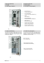
2.2  Elektrische Anschlüsse 

  2.2  Electrical Connections 

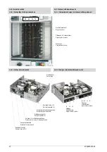
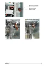
2.2.1 Kabelraum Frontanschluss


2.2.1  Cable compartment, front access 

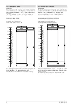
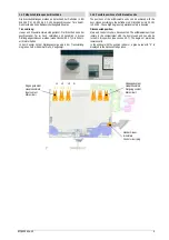
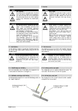
2.2.1.1  Kabelanschluss Hauptstromkreis 

  2.2.1.1  Cable connection, main circuit


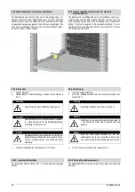
Kabel für die Hauptstromkreise in den Kabelraum einführen und mit 

Schellen an den rechts im Kabelraum liegenden Kabeltragschienen 

befestigen (siehe Betriebsanleitung 8PQ9800-1AA45). Beim Ausfor-

men und Ablängen der Kabel darauf achten, dass unnötige Zug- 

oder Schubkräfte auf die Anschlussplatte vermieden werden.  

Freiflächen für die Kabeleinführung siehe Betriebsanleitung  

8PQ9800-0AA12 Abschnitt 2.1. 

Die Außenleiter L1, L2, L3 entsprechend dem Stromlaufplan an die 
feststehenden, gekennzeichneten Anschlussstücke der Anschluss-

platte mit Sechkantschrauben anschließen.  


Achtung 


Beim Aufbringen des Drehmomentes auf der Mut-

ternseite ist am Schraubenkopf gegenzuhalten!  


Feed cables for main circuits into the cable compartment and fasten 

with clips to cable brackets on the right in the cable compartment (see 

Operating Instructions 8PQ9800-1AA45). When forming cables and 

cutting to length, avoid unnecessary tensile or thrust forces on the 

connecting plate. 

Free space required for cable entry, see Operating Instructions 

8PQ9800-0AA12, section 2.1. 

Connect the phase conductors L1, L2, L3 in accordance with the 
circuit diagram to the fixed terminal pieces on marked terminals on the 

terminal plate with hexagonal screws. 


Notice 


When applying torque to the nut, the screw head 

must be pressed firmly in the opposite direction! 


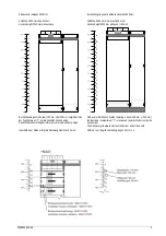
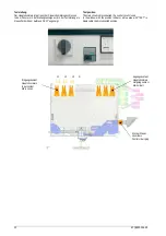
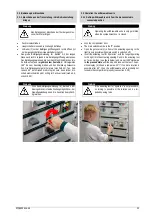
Eine Unterteilung entsprechend Form 4b kann mit Hilfe von Falten-

bälgen über dem Kabelanschluss erreicht werden. Den Faltenbalg 

bei Anschluss von Einzelkabeln je Anschlusslasche vor dem 

Aufquetschen des Kabelschuhs überziehen. Nach Anschluss des 

Kabels an die Lasche der Anschlussplatte wird der Faltenbalg über 

den Kabelschuh und bei Anschluss in der Anlage von vorn über den 

Kragen am Anschlussterminal gezogen. Anschließend wird das 

kabelseitige Ende soweit nachgeschoben, dass das Ende auf der 

Lasche nicht zurückrutscht. Bei Anschluss in der Anlage von hinten 

wird der Faltenbalg direkt auf der Schiene mit einem Kabelband 

befestigt. 

Sitzt der Faltenbalg nicht fest auf dem Kabel, so ist er mit Kabelband 

zu fixieren. Bei Anschluss von zwei Kabeln pro Anschlusslasche ist 

es erforderlich, die kabelseitige Tülle des Faltenbalgs im ersten Ring 

abzuschneiden. Nicht verwendete Anschlusslaschen sind mit einer 

Verschraubung zu versehen und mit einem mit Kabelband fixierten 
Faltenbalg zu abzudecken. 


Division according to form 4b can be achieved with the aid of bellows 

over the cable connection. When connecting individual cables, push 

the bellows over each terminal lug before crimping on the cable lug. 

After connecting the cable to the lug on the plate, the bellows are 

pushed over the cable lug and for cable connection from front over the 

flange at the terminal block. The cable-side end is then pushed up 

until the opposite end on the link does not slip back from the plate. 

The bellows are to fasten with cable strips directly on the bar at 

switchboards with connections from rear. 

If the bellows are not firmly on the cable, they must be fixed with cable 

strips. If more than two cables per terminal lug are connected, the 

cable-side sleeve of the bellows must be cut off at the first ring. 

Not used terminals must be bolted and covered by a bellow that is 

fixed with a cable strip. 


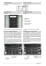
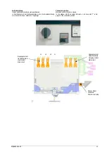
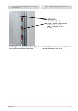
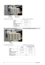
Der Kabelanschluss des PE-Leiters erfolgt an der vertikalen PE- 

Schiene mit Universal-Leiter-Anschlussklemmen oder Kabelschuhen. 

Der Kabelanschluss des N-Leiters (bei 3-poligen Einschüben) erfolgt 

an die vertikale N-Schiene im Kabelanschlussraum mit Kabelschu-

hen (mögliche Anschlussquerschnitte und Anziehdrehmomente siehe 

Abschnitt 2.2.1.2, Ausführung der Verschraubungen nach Betriebs-
anleitung 8PQ9800-1AA45). 


The cable connection of PE- conductor to the vertical PE-bar is car-

ried out with universal-conductor-terminals or cable lugs. The N-

conductor (if 3-pole withdrawable units) must be connected to the 

vertical N-bar in the cable connection compartment (possible cable 

cross-sections and tightening torques see section 2.2.1.2, execute the 

screw connection according operating instruction 8PQ9800-1AA45). 


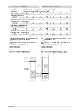
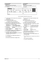
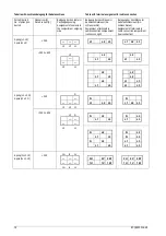
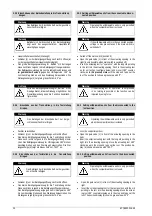
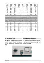
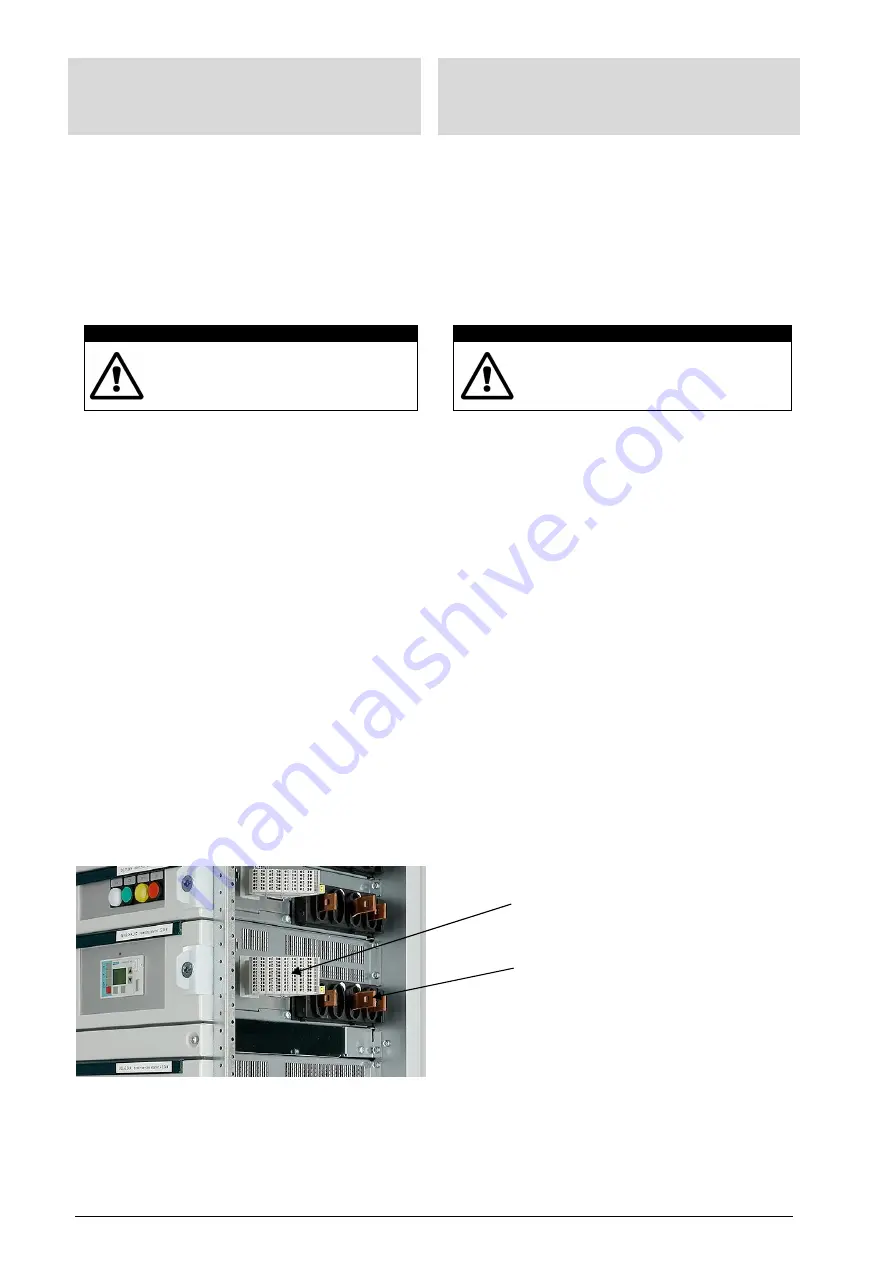
Klemmen Hauptstromkreis (bis 250A) 
Main circuit terminals (up to 250A) 

Klemmen Steuerstromkreis 
Control circuit terminals 

Summary of Contents for SIVACON S 8PQ Series

Page 1: ... pericolosa Può provocare morte o lesioni gravi Scollegare l alimentazione prima di eseguire interventi sull apparecchiatura L installazione e la manutenzione di questo apparecchio devono essere effettuati solo da un elettrotecnico autoriz zato PT PERIGO Tensão perigosa Perigo de morte ou ferimentos graves Desligue a alimentação elétrica e proteja contra o religamento antes de iniciar o trabalho n...

Page 2: ... įtampą Šio įrenginio įrengimo ir techninės priežiūros darbus leidžiama atlikti tik įgaliotam elektrikui MT PERIKLU Vultaġġ perikoluż Riskju ta mewt jew korriment serju Itfi u sakkar il provvista kollha tad dawl li tkun qed tforni d dawl lil dan it tagħmir qabel ma taħdem fuq dan it tagħmir Ix xogħlijiet ta installazzjoni u manutenzjoni fuq dan it tagħmir jist għu jitwettqu biss minn elettriċista ...

Page 3: ...eller gewährleistet Reliable functioning of the equipment is only ensured with compo nents from original manufacturer Inhalt Seite Content Page 1 1 1 1 1 1 1 1 2 1 1 3 1 2 1 3 1 3 1 1 3 2 1 3 3 1 4 1 4 1 1 4 2 1 4 3 1 4 3 1 1 4 3 2 1 5 Beschreibung des MCC Feldes Feldaufbau Beschreibung des Feldaufbaues Varianten der Feldbestückung Einbauortkennzeichnung Maximale Feldgewichte Vertikale Feldschiene...

Page 4: ...28 29 29 29 29 30 31 31 31 32 33 33 33 34 35 36 37 38 38 2 2 1 2 2 2 2 1 2 2 1 1 2 2 1 2 2 2 2 2 2 2 1 2 2 2 2 3 3 1 3 1 1 3 1 2 3 1 3 3 2 3 2 1 3 2 2 3 2 3 3 2 4 3 2 5 3 2 6 3 2 7 3 2 8 3 2 9 3 2 10 4 4 1 4 2 4 2 1 4 2 2 4 3 4 3 1 4 3 2 4 3 3 4 4 4 4 1 4 4 2 4 4 2 1 4 4 2 2 4 4 2 3 4 4 2 4 4 4 2 5 5 Mounting Access to main busbar joint for main busbar at rear Electrical connections Cable compartm...

Page 5: ...ed design see Operating instructions 8PQ9800 1AA50 Additionally it is possible to integrate an adapter for 3NJ6 in line switch disconnector below in the cubicle Fig 2 Bereich mit Einschüben Area for withdrawable units Bereich mit Abzweigen in Festeinbau Area with feeders in fixed mounted design Bereich mit Lasttrennschalter 3NJ6 Area with switch disconnector 3NJ6 Querverdrahtungsraum Transverse wi...

Page 6: ...on height 2200 mm without base Feldhöhe 2200 mm mit Sockel 100 mm Section height 2200 mm with base 100 mm 2000 1800 1600 1400 1200 1000 800 600 400 200 0 2200 SIEMENS SIVACON SIEMENS SIVACON A B C D E F G H J K L M N P Q R S T U V 2000 1800 1600 1400 1200 1000 800 600 400 200 0 2200 SIEMENS SIVACON SIEMENS SIVACON A B C D E F G H J K L M N P Q R S T U V A B A B A B A B A B A B A B A B A B A B A B ...

Page 7: ...00 mm oder 200 mm vergrößert sich der Funktionsraum T um die Sockelhöhe nach unten Das Millimeterraster beginnt immer am unteren Ende der Anlage With power distribution boards featuring a base 100 mm or 200 mm the functional compartment T is increased towards the bottom by the base height The millimeter grid always starts at the bottom end of the board Innerhalb einer Reihe erfolgt die Rasterung N...

Page 8: ...hes angeordnet Die Öffnungen im Steckschienenkanal oberhalb des Shutters in diesem Fach sind bei Ausführung mit Shutter mit dem gleichen Teil abge deckt nur dass das Entfernen der oberen Fahnen an diesem Teil entfällt Für weitere Information siehe 4 4 2 1 For the withdrawable units an optional shutter can be supplied for locking the openings for the contacts in the plug in duct The shutter has a t...

Page 9: ...fer nicht bei Hauptsammelschiene hinten Flat copper not with main busbar at rear 1x40x10 985 955 925 895 860 830 795 2x40x10 1240 1200 1160 1120 1080 1040 995 Bei Sammelschienenlage hinten kann die Stromteilung im Verhältnis 5 zu 1 genutzt werden d h zusätzlich bis 520 A Beispiel Bemessungsstrom 1620 A Summenstrom aus Höhe 1462 mm 1100 A Summenstrom aus Höhe 337 mm 520 A 1 1520 A 1000 A 520 A 2 16...

Page 10: ... The basic design is supplemented by a mounting plate for the equipment The withdrawable units are available for the following compartment heights 100 150 200 250 300 400 500 600 700 and 800 mm Each withdrawable unit has its own compartment door Normaleinschübe in PROFINET Ausführung Additiv zum Steuerstecker sind bis zu zwei PROFINET Stecker möglich Standard withdrawable units PROFINET version Up...

Page 11: ...ssener Tür im Fach verbleiben und zusätzlich in dieser Stellung abgeschlossen werden siehe Abschnitt 3 2 7 Die Schutz art bleibt erhalten In dem Fenster mit der Stellungsanzeige wird in der Trennstellung ein grünes Feld mit dem Aufdruck 0 angezeigt Disconnected position Main and control circuit are disconnected The withdrawable unit can remain in the compartment with the door closed and can also b...

Page 12: ...em Aufdruck TEST angezeigt Test position The main circuit is disconnected the control circuit closed In the window with the position indicator a blue area with TEST is displayed in the disconnected position L1 L2 L3 N Eingangskontakt Hauptstromkreis Input contact Main circuit Abgangskontakt Hauptstromkreis Outgoing contact Main circuit Stecker Steuer stromkreis Control circuit plug ...

Page 13: ... mit dem Aufdruck I angezeigt Connected position Main and control circuit are closed In the window with the position indicator a red area with I is dis played in the connected position L1 L2 L3 N Eingangskontakt Hauptstromkreis Input contact Main circuit Abgangskontakt Hauptstromkreis Outgoing contact Main circuit Stecker Steuer stromkreis Control circuit plug ...

Page 14: ...takte Openings for contacts Fachboden Compartment bottom L1 L2 L3 N N L3 L2 L1 Eingangs kontaktsystem Input contact system L1 L2 L3 Abgangs Kontaktsystem Output contact system Rasthebel rechts 3 Ratchet lever right 3 Instrumententafel aufschwenkbar Instrument panel rotatable Schieber 1 vor Betätigungsöffnung Gate valve 1 in front of opening for tools Hauptschalterantrieb Actuation for main switch ...

Page 15: ...ür Motorabzweige der Starterkombination Hersteller Ident Code der Fertigungseinheit Die Summe der Angaben muss die eindeutige Kennzeichnung der Fertigungseinheit Typical gewährleisten A B C Fertigungsstätte und vollständige Kundenauftragsnummer Stromlaufplanname Zählnummer innerhalb identischer Fertigungseinheiten Space for customer specific identifier or identification code of functional unit Rat...

Page 16: ...eststellen erden und kurzschließen Alle Vor schriften und betrieblichen Sicherheitsanforde rungen beachten Warnung Um Verletzungen zu vermeiden wird empfohlen bei der Montage Handschuhe zu tragen Danger Hazardous voltage Touching the live parts results in death or severe personal injury Only qualified personnel may operate the system they must be familiar with the instructions and in particular ob...

Page 17: ...sammelschienenverbundes ist in der Be triebsanleitung 8PQ9800 1AA44 Abschnitt 3 beschrieben The manufacture of the main busbar combination is described in the Operating Instructions 8PQ9800 1AA44 section 3 Kabelanschlussraum Cable connection compartment Öffnungen für den Zugang zur Herstellung des Hauptsammelschienenverbunds Openings for access for main busbar combination ...

Page 18: ...ss in der Anlage von hinten wird der Faltenbalg direkt auf der Schiene mit einem Kabelband befestigt Sitzt der Faltenbalg nicht fest auf dem Kabel so ist er mit Kabelband zu fixieren Bei Anschluss von zwei Kabeln pro Anschlusslasche ist es erforderlich die kabelseitige Tülle des Faltenbalgs im ersten Ring abzuschneiden Nicht verwendete Anschlusslaschen sind mit einer Verschraubung zu versehen und ...

Page 19: ...Anschluss von einem Kabel Connection of one cable Anschluss von zwei Kabeln Connection of two cables Klemmen Hauptstromkreis bis 630A Main circuit terminals up to 630A Klemmen Steuerstromkreis Control circuit terminals ...

Page 20: ...minals in cable connection compartment connection right Belegung der Anschlüsse im Kabelanschlussraum An schluss hinten Assignment of terminals in cable connection compartment rear connection 3 polig L1 L3 3 pole L1 L3 250 L3 L2 L1 L1 L2 L3 L1 L2 L3 250A 630 L2 L3 L1 L2 L1 L3 L2 L1 L3 L2 L1 L3 L2 L1 L3 L2 L2 L1 L3 L1 L3 4 polig L1 L3 N 4 pole L1 L3 N 250 N L3 L2 L1 N L1 L2 L3 N L1 L2 L3 250A 630 L...

Page 21: ...erden For cables with small cross sections suitable terminals can be used 2 2 2 Steuerstromkreise 2 2 2 Control circuit Steuerleitungen an Kabeltrageisen befestigen Die Leitungen zum Querverdrahtungsraum sind durch die vorgesehenen Ausbrüche zu führen bei Anschluss in der Anlage von hinten durch den oben liegenden Kabelkanal nach vorne in den Querverdrahtungsraum Die Steuerleitungen werden gemäß S...

Page 22: ...terminal block with screw terminal Klemmquerschnitte je Anschlussstelle Clamping cross section per connection point 1 Leiter 1 conductor 2 Leiter gleichen Querschnitts 2 conductors with same cross section eindrähtig solid 0 35 2 5 mm2 0 35 1 5 mm2 flexibel flexible 0 35 2 5 mm2 0 35 1 5 mm2 Feindrähtig mit Aderendhülse Finely stranded with end sleeve 0 25 2 5 mm2 0 25 1 0 mm2 Anziehdrehmoment Nm T...

Page 23: ... the low voltage switchgear isolate the switchgear including auxiliary voltage ensure it does not switch on again verify that it is free of voltage and earth and short circuit it 3 1 Inbetriebnahme 3 1 Commissioning Die Inbetriebnahme erfolgt mit Ausnahme der folgenden Abweichun gen und oder Ergänzungen gemäß Betriebsanleitung SIVACON S8 8PQ9800 1AA46 Achtung Je nach Anlagenkonfiguration können in...

Page 24: ...on Schutzorganen Leistungsschalter Überlastrelais etc und die Parametrisierung von Steuerorganen SIMOCODE etc unter Berücksichtigung der örtli chen Netzverhältnisse und Betriebsbedingungen festzulegen und einzustellen Hierbei sind ggf vorhandene Vorgaben auf den Leis tungsschildern der Abzweige zu maximal zulässigen Einstellwerten zu beachten Notice As it is not possible to cover all special desig...

Page 25: ...4 zeigt ein rotes Feld mit I an Soll te nach 60 kein Drehen mehr möglich sein dann ist der Ein schub wahrscheinlich nicht richtig im Fach verrastet siehe Ab schnitt 3 2 5 Lock the compartment door The main switch must be in the 0 position Open the gate valve 1 in front of the actuating opening to the right is only possible when main switch is switched off Insert the actuating tool for operation wi...

Page 26: ...an be impaired by using force 3 2 3 Einschübe aus der Trennstellung in die Teststellung bringen 3 2 3 Setting withdrawable units from the disconnected to the test position Warnung Das Betätigen der Einschübe darf nur bei ge schlossener Fachtür erfolgen Warning Operating the withdrawable units is only permitted when the compartment door is closed Fachtür verschließen Schieber 1 vor der Betätigungsö...

Page 27: ...e vice mounting plate can be gripped Avoid any mechanical stress and deformation of main and con trol voltage contacts when handling the withdrawable unit out side the compartment Warning The lifting of heavy withdrawable units 20 kg can lead to physical injuries Unsafe handling with heavy weights can easily lead to damage to property Einsetzen des Einschubes in das Fach Öffnen der Fachtür Prüfen ...

Page 28: ...ists of an outer and an inner disk which can be turned in opposite directions to each other There are 96 possible variations based on the different positions The position of the two disks in the compartment is turned and mirrored by 180 to the position in the withdrawable unit Thus the letter number assignments between compartment and withdrawable unit are different see diagrams and table below Au...

Page 29: ... 1 B 8 G 10 B 11 G 7 B 2 H 4 A 5 H 1 A 8 H 10 A 11 H 7 A 3 A 3 H 6 A 12 H 9 A 9 H 12 A 6 H 3 B 3 G 6 B 12 G 9 B 9 G 12 B 6 G 3 C 3 F 6 C 12 F 9 C 9 F 12 C 6 F 3 D 3 E 6 D 12 E 9 D 9 E 12 D 6 E 3 E 3 D 6 E 12 D 9 E 9 D 12 E 6 D 3 F 3 C 6 F 12 C 9 F 9 C 12 F 6 C 3 G 3 B 6 G 12 B 9 G 9 B 12 G 6 B 3 H 3 A 6 H 12 A 9 H 9 A 12 H 6 A 3 2 7 Abschließbarkeit von Einschüben 3 2 7 Locking capability of withd...

Page 30: ...tellung bringen siehe Abschnitt 3 2 1 Warnung Das Einschalten muss betrieblich zulässig sein Vorsicht Das Einschalten ist nur möglich wenn der Schieber 1 siehe Abschnitt 3 2 1 die Betätigungsöffnung vollständig verschlossen hat Gefahr Bei eingeschaltetem Hauptschalter mit Einschub in Betriebsstellung befindet sich der Hauptstromkreis und der Steuerstromkreis des Einschubs unter Spannung Griff des ...

Page 31: ...4 1 Inspektion 4 1 Inspection Die Inspektion ist nach der Betriebsanleitung 8PQ9800 1AA46 Kapitel 2 3 durchzuführen Folgende Kontrollen sind zusätzlich durchzuführen wobei der Einschub aus dem Feld genommen und in eine Absetzstellung gebracht werden muss Sichtkontrolle des Einschubkontakte Sichtkontrolle und Funktionstest der Einschubmechanik Sichtkontrolle eventuell vorhandener Shutter The inspec...

Page 32: ...erelctric KR 44 102 Klüber Lubrication http www klueber com maintenance intervals see operating In struction 8PQ9800 1AA46 section 2 2 The main contacts have to be driven out at the normal withdrawable unit a little turn the key about 90 see pictures step 1 Please observe the two levers at the left and right hand side in front must be at lowest position thereby Apply grease as a thin layer only on...

Page 33: ...st be found and eliminated The circuits and any devices which experienced a fault current must be inspected regarding potential damages and reconsti tution of operability Contactors in main circuit must be checked for welded switch ing contacts Any existing weldings have to be broken open or the device has to be exchanged if the proper functioning can not be restored see operating instructions of ...

Page 34: ...mperatures of up to 130 C during operation Warning Please do not operate withdrawable units with LV HRC fuse bases without the cover NH Sicherungseinsatz Geeigneter Aufsteckgriff Größe 00 Best Nr 8PQ9400 1AA50 Größe 0 bis 3 Best Nr 8PQ9400 1AA51 LV HRC fuse Suitable fuse puller Size 00 Order No 8PQ9400 1AA50 Size 0 to 3 Order No 8PQ9400 1AA51 4 3 3 Austausch von Geräten 4 3 3 Renewing of devices W...

Page 35: ...of the protection devices and same fuse type is ensured Before you insert a new withdrawable unit please check if the contacts are in discon nected position Warning compartments with shutter must only be used with withdrawable units containing the shutter actuation 4 4 2 Einschubfächer umrüsten 4 4 2 Re equipping withdrawable unit compartments Während der Arbeiten darf die Anlage unter folgenden B...

Page 36: ...nenabdeckung und dem Shutter deckungsgleich sind die darüber liegenden Abdeckungen müssen unbeweglich sein 5 Einsetzen der Shutterverriegelung e links im Fach Abb D und anschließendes Eindrücken nach hinten bis die M6 Schraube f durch den Ausschnitt im Shutterverschluss hindurch am Fachbo den angeschraubt werden kann Abb E 6 Zusammensetzen des Shutterverschlusses für die rechte Seite g und einsetz...

Page 37: ... und diese anheben dabei Shutter nach unten drücken Abb G Wenn die Nasen der Feldschienenabdeckung die förmigen Ausschnitte im Shutter freigeben diesen nach vorn abheben und heraus nehmen Abb H Remove the shutter fastener components in reverse order fig D E F Lift the two little flaps d with a small screw driver and push the shutter downwards fig G When the pins of the cover release the shaped win...

Page 38: ...osen screw below right in the middle of the compartment between compartment bottom and separating plate Lift lowest vertical separating plate and swivel out inwards Lift connecting terminal to the right approx 10 mm push left and lift up see figure below Einbau Den linken unteren Haken vom Anschlussterminal hinten in das Loch im Fachboden einführen siehe Bild Anschlussterminal rechts leicht angeki...

Page 39: ...dem Abgangsge häuse zu liegen kommt Abb D Abgangsgehäuse nach links schieben 1 nach hinten bewegen 2 und nach oben 3 aus der Verankerung im Fachboden lösen und heraus nehmen Abb E Falls die Steuerleitungen auch getauscht werden Blechkanal f im Kabelanschlussraum abschrauben Klemmblock von Hut schiene abnehmen und komplette Steuerverdrahtung mit Trag blech der Steuerleitungsbuchse herausnehmen Einb...

Page 40: ...tz eingeführt wird The terminal outgoing feeder housing must be removed before hand Shutter fastener and parts of additional internal separation 8PQ5001 7AA56 if used in this compartment must be re moved beforehand refer to 4 2 2 2 If there is a mechanical coding the two screws a at the rear of the plate must be removed and the plate taken out Remove the thread forming screws at the rear of the pl...

Reviews: