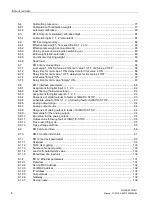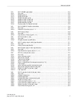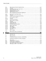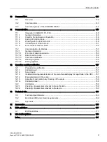
Table of contents
SIWAREX WP231
12
Manual, 07/2014, A5E31238908A-02
Figure 6-1
SIWAREX WP231 connection areas ........................................................................................... 29
Figure 6-2
Shielding in the screw gland ........................................................................................................ 31
Figure 6-3
Shield connection element fitting (example) ................................................................................ 32
Figure 6-4
Connection of strain gauge load cell(s) with 4-wire system ......................................................... 33
Figure 6-5
Connection of strain gauge load cell(s) with 6-wire system ......................................................... 34
Figure 6-6
Connection of Siebert display S102 ............................................................................................. 39
Figure 6-7
Mounting of the calibration protection plate ................................................................................. 42
Figure 7-1
Quick start step 1 ......................................................................................................................... 45
Figure 7-2
Quick start step 2 ......................................................................................................................... 46
Figure 7-3
Quick start step 3 ......................................................................................................................... 47
Figure 7-4
Quick start step 4a ....................................................................................................................... 48
Figure 7-5
Quick start step 5a ....................................................................................................................... 49
Figure 7-6
Quick start step 4b ....................................................................................................................... 50
Figure 7-7
Quick start step 5b ....................................................................................................................... 51
Figure 7-8
Quick setup with marked parameters .......................................................................................... 52
Figure 7-9
Sending/receiving a data record with SIWATOOL V7 ................................................................. 53
Figure 7-10
Layout of the SIWATOOL user interface ..................................................................................... 55
Figure 7-11
Sending/receiving a data record with SIWATOOL V7 ................................................................. 56
Figure 7-12
Trace export ................................................................................................................................. 59
Figure 7-13
Downloading the firmware with SIWATOOL ................................................................................ 61
Figure 8-1
Standstill monitoring ..................................................................................................................... 73
Figure 8-2
Step-forced response of the digital low-pass filter when f = 2 Hz ................................................ 74
Figure 8-3
Calibration digits and calibration weight ....................................................................................... 78
Figure 8-4
Linearizing the scales' characteristic curve .................................................................................. 79
Figure 8-5
Limit value configuration .............................................................................................................. 86
Figure 11-1
Configuration in the TIA Portal "HW catalog" ............................................................................. 146
Figure 11-2
Configuration with S7-1212 CPU ............................................................................................... 147
Figure 11-3
Start address of module in TIA Portal ........................................................................................ 147
Figure 11-4
HW ID of module in TIA Portal ................................................................................................... 147
Figure 11-5
Calling of WP231PR block in user program ............................................................................... 148
Figure 11-6
CMD command mailboxes ......................................................................................................... 149
Figure 13-1
Current ranges for signal level to Namur recommendation NE43 ............................................. 165
Figure A-1
Electrostatic voltages which an operator can be subjected to ................................................... 178
Summary of Contents for SIWAREX WP231
Page 16: ...Safety notes 2 1 General safety instructions SIWAREX WP231 16 Manual 07 2014 A5E31238908A 02 ...
Page 132: ......
Page 174: ...Technical data 13 3 Approvals SIWAREX WP231 174 Manual 07 2014 A5E31238908A 02 ...
Page 180: ...List of abbreviations SIWAREX WP231 180 Manual 07 2014 A5E31238908A 02 ...
Page 182: ...Index SIWAREX WP231 182 Manual 07 2014 A5E31238908A 02 ...


