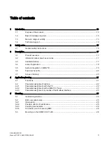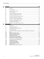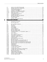
Table of contents
SIWAREX WP231
6
Manual, 07/2014, A5E31238908A-02
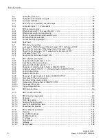
8.4
Calibration procedure ............................................................................................................. 77
8.4.1
Calibration with calibration weights ........................................................................................ 77
8.4.2
Automatic calibration .............................................................................................................. 80
8.5
DR 4 Output of calculated calibration digits ........................................................................... 81
8.5.1
Calibration digits 0, 1, 2 (calculated) ...................................................................................... 81
8.6
DR 5 zeroing memory ............................................................................................................ 82
8.6.1
Effective tare weight - from specification 1, 2 or 3 ................................................................. 83
8.6.2
Effective tare weight (semi-automatic) ................................................................................... 83
8.6.3
Zero by power-on (value when switching on) ........................................................................ 83
8.6.4
Zero weight (semi-automatic) ................................................................................................ 83
8.6.5
Current zero tracking weight .................................................................................................. 83
8.6.6
Dead load ............................................................................................................................... 83
8.7
DR 6 limit value settings ........................................................................................................ 84
8.7.1
Limit value 1 ON, limit value 2 ON, limit value 1 OFF, limit value 2 OFF .............................. 86
8.7.2
Delay time for limit value 1 ON, delay time for limit value 2 ON ............................................ 86
8.7.3
Delay time for limit value 1 OFF, delay time for limit value 2 OFF ........................................ 86
8.7.4
Limit value "Empty" ON .......................................................................................................... 87
8.7.5
Delay time for limit value "Empty" ON .................................................................................... 87
8.8
DR 7 interface parameters ..................................................................................................... 88
8.8.1
Assignment for digital input 0, 1, 2, 3 ..................................................................................... 92
8.8.2
Input filtering (hardware setting) ............................................................................................ 92
8.8.3
Assignment for digital output 0, 1, 2, 3 .................................................................................. 92
8.8.4
Response of digital outputs to faults or SIMATIC STOP ....................................................... 93
8.8.5
Substitute value for DQ 0, 1, 2, 3 following fault or SIMATIC STOP ..................................... 93
8.8.6
Analog output range ............................................................................................................... 94
8.8.7
Analog output source ............................................................................................................. 94
8.8.8
Response of analog output to faults or SIMATIC STOP........................................................ 94
8.8.9
Start value for the analog output ............................................................................................ 94
8.8.10
End value for the analog output ............................................................................................. 94
8.8.11
Output value following fault or SIMATIC STOP ..................................................................... 95
8.8.12
Trace recording cycle ............................................................................................................. 95
8.8.13
Trace storage method ............................................................................................................ 95
8.9
DR 8 date and time ................................................................................................................ 96
8.10
DR 9 module information ....................................................................................................... 97
8.11
DR 10 load cell parameters ................................................................................................... 99
8.11.1
Overview ................................................................................................................................ 99
8.11.2
50/60 Hz toggling ................................................................................................................. 100
8.11.3
Number of support points ..................................................................................................... 100
8.11.4
Load cell characteristic value ............................................................................................... 100
8.11.5
Rated load of a load cell ...................................................................................................... 100
8.12
DR 12 Ethernet parameters ................................................................................................. 101
8.12.1
Overview .............................................................................................................................. 101
8.12.2
Device MAC address ........................................................................................................... 102
8.12.3
Port MAC address ................................................................................................................ 102
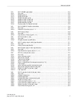
8.12.4
IP address ............................................................................................................................ 102
8.12.5
Subnet mask ........................................................................................................................ 102
8.12.6
Gateway ............................................................................................................................... 102
8.12.7
Device name ........................................................................................................................ 102
Summary of Contents for SIWAREX WP231
Page 16: ...Safety notes 2 1 General safety instructions SIWAREX WP231 16 Manual 07 2014 A5E31238908A 02 ...
Page 132: ......
Page 174: ...Technical data 13 3 Approvals SIWAREX WP231 174 Manual 07 2014 A5E31238908A 02 ...
Page 180: ...List of abbreviations SIWAREX WP231 180 Manual 07 2014 A5E31238908A 02 ...
Page 182: ...Index SIWAREX WP231 182 Manual 07 2014 A5E31238908A 02 ...


