background image

Document Number: 129-369 
Installation Instructions 
September 30, 2002 

Installation 

If you are mounting an actuator on a new valve, begin 
with the instructions in Figure 3.  

Removing the Actuator  
from the Valve  

1.  Remove the actuator cover. 

2.  Disconnect the wires and conduit, if installed. 

3.  Loosen the valve stem retainer using a 5 mm hex 

wrench and lower the valve stem into the valve.  

4.  Loosen the yoke nuts in the actuator yoke using a 

5 mm hex wrench. 

5.  Remove the actuator from the valve, use care not 

to damage the valve stem. 

Continue with 

Mounting an Actuator to a Valve

EA0134R1


Figure 3.  Preparing a new Valve.


Mounting an Actuator to a Valve. 

NOTE: 

Install the packing heating element,  
(P/N 599-00417), if used, before proceeding. 


EA0380R1

5 mm

3x360

°

5 x 360

°

«MAN

«MAN «


Figure 4.  

NOTE: 

Make sure the yoke nuts are loose enough to 
allow the actuator to slip over the bonnet. 
See Figure 5.  


EA0382R1


3


Figure 5. 


EA0384R1

5 mm


5


Figure 6. 

NOTE: 

Hold the stem retainer in place as you tighten 
it around the valve stem. See Figure 6. 

EA0383R2

5 mm

MAX. TORQUE

40 lb-in (4.5 Nm)


6

6


1


Figure 7.


NOTE: 

Position the actuator to accommodate the 
wiring. Hold the actuator in place while 
tightening the yoke nuts. See Figure 7. 

EA0381R1

>3x360

°

«AUTO «


2

7

Page 2 of 6 

Siemens Building Technologies, Inc. 

Figure 8. 

Summary of Contents for SKD62UA

Page 1: ...m hex wrench Small and medium flat blade screwdrivers Expected Installation Time 20 minutes for factory installed actuator 45 minutes for field replacement of actuator Prerequisites WARNING If mounting the actuator to a valve already in line either close the shut off valves in the piping upstream first then downstream or switch off the pump to allow the differential and static pressure in the valv...

Page 2: ...th Mounting an Actuator to a Valve EA0134R1 Figure 3 Preparing a new Valve Mounting an Actuator to a Valve NOTE Install the packing heating element P N 599 00417 if used before proceeding EA0380R1 5 mm 3x360 5 x 360 MAN MAN Figure 4 NOTE Make sure the yoke nuts are loose enough to allow the actuator to slip over the bonnet See Figure 5 EA0382R1 4 3 Figure 5 EA0384R1 5 mm 5 Figure 6 NOTE Hold the s...

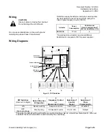
Page 3: ...ring Diagrams EA1077R1 LED Status Indication Stroke Calibration Rotary Switches LO and UP Connection Terminals G0 AC 24V 50 60Hz 0 10V 4 20mA G G0 Chm G Y M U Z OK Green Status Calib Red Calib Error Valve Jam 1 2 3 4 Figure 9 DIP Switches DIP Switches From Left to Right 1 Select Direction of Operation 2 Sequence Control or Stroke Limit Control 3 Selection of Control Signal 4 Selection of Flow Char...

Page 4: ...ecessary To initiate the calibration procedure short circuit the contacts inside the slot located on the printed circuit board with a screwdriver Automatic calibration proceeds as follows Actuator runs to the 0 stroke position 1 the green LED flashes Actuator then runs to the 100 stroke position 2 the green LED flashes 0 1 2 3 y 100 Stroke EA1066R1 Measured values are stored in the EPROM The actua...

Page 5: ...tion Manual Operation EA1080R1 MAN AUTO AUTO 3x360 1 0 0 1 0 0 1 0 1 0 1 0 1 EA0387R1 3 4 in 20mm Figure 11 Manual Override in Manual and Automatic Position Each complete revolution 360 is equal to 3 32 inch 2 5 mm stroke Reference Technical Instruction Document Number EA599 18 Flowrite 599 Series SKB C D 62UA Series Electronic Valve Actuator 24 Vac Proportional Control Advanced Features 155 717 F...

Page 6: ...13 16 300 4 3 4 120 0 1 0 1 1 0 EA0385R1 Information in this publication is based on current specifications The company reserves the right to make changes in specifications and models as design improvements are introduced Flowrite is a trademark of Siemens Building Technologies Inc Other product or company names mentioned herein may be the trademarks of their respective owners 2002 Siemens Buildin...

Reviews: