Document No. 997-1002
Installation Instructions
February 12, 2009
Page 4 of 8
SLX Series
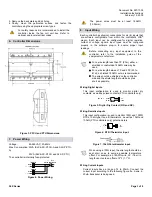
Figure 8: Current Input – 2-Wire Transducer.
Connect the current input according to the following figure if
a 3-wire, 4-20mA transducer is being used.
Figure 9: Current Input – 3-Wire Transducer.
Connect the current input according to the following figure if
the transducer is powered by its own power source.
Figure 10: Current Input – Transducer with its Own
Power Source.
Wiring Voltage Inputs
Voltage inputs have a range of 0 to 10VDC. Connect the
voltage input according to the following figure if a 3-wire 0-
10V transducer is being used.
Figure 11: Voltage Input – 3-Wire Transducer.
Connect the voltage input according to the following figure if
the transducer is powered by its own power source.
Figure 12: Voltage Input – Transducer with its Own
Power Source.
On the SLX-ASC-PFCU-A and SLX-P-PTU-A, the
onboard 24VAC output with a DC power supply can
be used to supply the current loop, as shown in
Figure 9. It can also be used to supply the voltage,
as shown in Figure 11
.
Refer to the transducer
installation guide for further details.
9. SLX-RTS/SLX-STAT
Wiring
Each controller is compatible with the SLX-RTS line of
standard room sensors. Refer to the SLX-RTS and SLX-STAT
installation instructions for wiring details.
10. Output Wiring
The SLX-ASC-PFCU and SLX-P-PTU controllers have
physical connections for four (4) relay contact outputs and four
(4) triac outputs. In addition to these outputs, the SLX-ASC-
PFCU-A and SLX-P-PTU-A controllers have two (2) universal
outputs. All of these outputs are software configurable.
Before connecting any input equipment to the
controller, refer to the installation guide of the
equipment manufacturer.
Wiring Relay Contact Outputs
Three (3) relay contact outputs (DO1-DO3) can switch 3A
(inductive/resistive) for fan speed control up to 277VAC, and
one (1) relay contact output (DO4) can switch 3A (inductive)
and 10A (resistive) for heater control up to 277VAC.
•
Relay contact output cables must remain
between 18 and 14AWG. Select the proper
gauge according to the current load.
•
All digital relay contact outputs on PFCU and
PTU controllers are normally open.
•
There is no voltage present on the digital output
terminals, so an external power supply should
be used if necessary.
•
It is recommended to use a 4A fast-acting, high-
breaking fuse to protect the relay contact outputs
(DO1-3) and a 15A fast-acting, high-breaking
fuse to protect the relay contact output (DO4)
against short circuiting when high voltage is
being used.
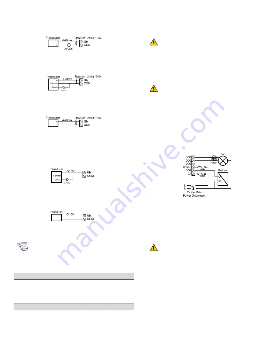
Figure 13: Relay Contact Output – Fan and Reheat
Powered by External 85-265VAC Power Supply.
Wiring Triac Outputs
The four (4) triac outputs can switch 1A at 20.4-265VAC and
can be used to turn equipment and devices on and off (two-
state outputs) and to control valve and damper actuators
using stroke time or Pulse Width Modulation (PWM).
•
Triac output cables should be between 20 and
18AWG. They must be at least 18AWG if they
are switching high voltage.
•
To measure the state of a triac output, an
external load must be connected.
•
When high voltage is used, you must use a 4A
fast-acting, high-breaking fuse to protect the
triac outputs against short circuiting.
•
It is not necessary to use a fuse when the
onboard 24VAC output is being used with the
triac outputs since it already has built-in short
circuit protection.
•
The triac outputs work in pairs (DO5-DO6 and
DO7-DO8) and cannot work with two different
voltages. For example, the DO5-DO6 switch
high voltage (85-265VAC) and DO7-DO8 switch
the onboard 24VAC.

