background image

Document No. 997-1002 

Installation Instructions 

February 12, 2009 


SLX Series


Page 7 of 8


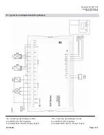
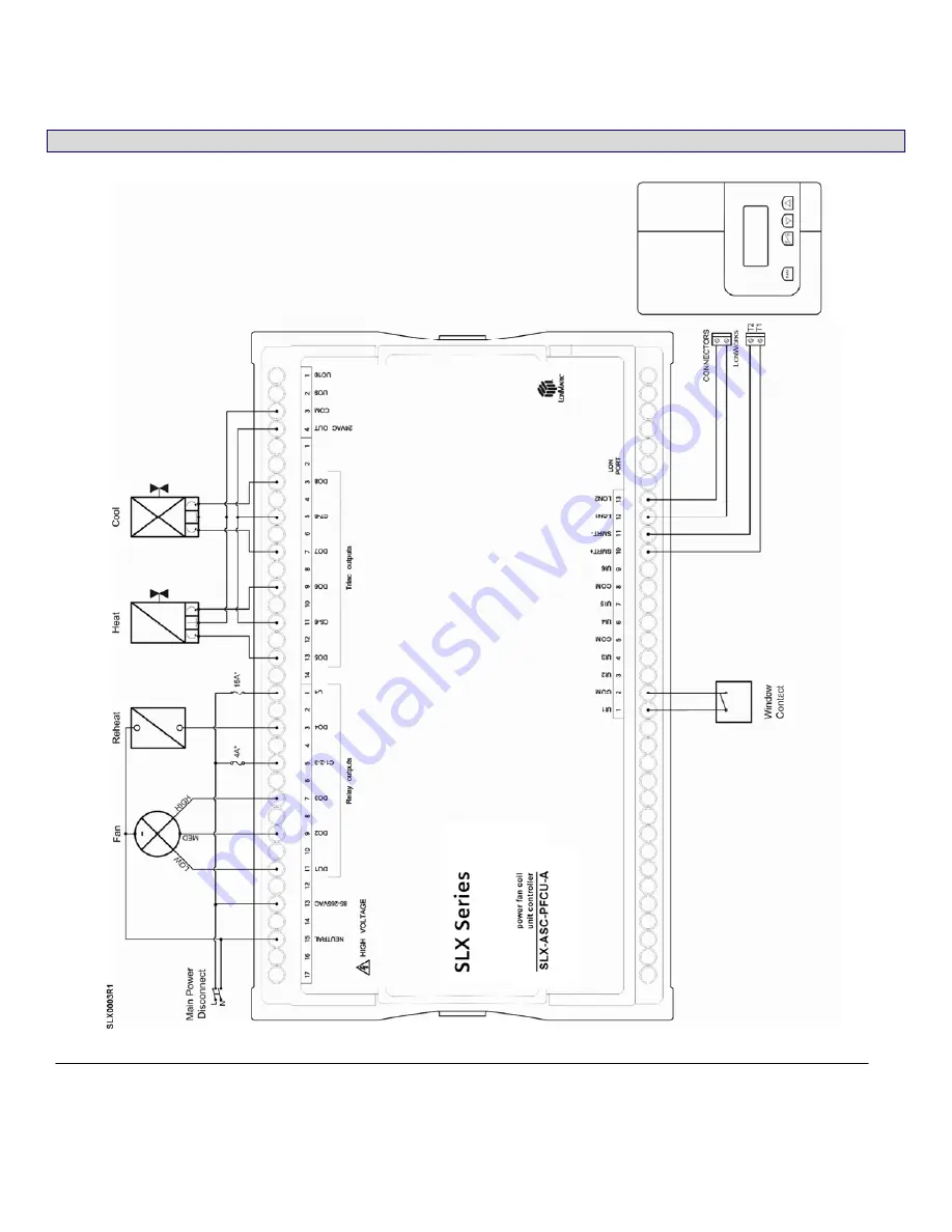
15.  Typical Fan Coil Application Wiring Diagram 


*4A – Fast-acting, high-breaking; 5 x 20mm 
Fuse PART#: 216 004XP (Littelfuse) 
Fuse holder PART#: 3004100 (Phoenix Contact) 

*15A – Fast-acting, high-breaking; 6 x 32mm 
Fuse PART#: 314015P (Littelfuse) 
Fuse holder PART#: 3004171 (Phoenix Contact) 

Summary of Contents for SLX-ASC-PFCU

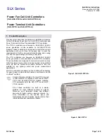
Page 1: ...illers and boilers Moreover they are suitable for any lighting control and power measurement applications All of the controllers are based on the LONWORKS technology for peer to peer communication between controllers and are LONMARK certified Unless otherwise indicated the term PFCU is used in this document to represent both the SLX ASC PFCU and SLX ASC PFCU A models Likewise PTU represents both t...

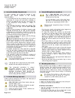
Page 2: ...electrical shock or burn Warning Symbol Significant information required Refer to Hardware Installation Guide Double Insulation Symbol These controllers are built with double insulation 4 General Wiring Recommendations Due to HIGH VOLTAGE direct contact will cause electrical shock or burn Turn off power before any kind of servicing It is recommended to use a 2 line main power disconnect to be loca...

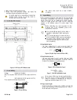
Page 3: ...h less than 75 23m either a shielded or unshielded 18AWG wire may be used For a wire length between 75 and 200 23 to 61m a shielded 18AWG wire is recommended The wire should be shielded on the controller side and the shield length should be kept as short as possible Wiring Digital Inputs This input configuration is used to monitor digital dry contacts as well as pulsed contacts PTU controllers onl...

Page 4: ... to the installation guide of the equipment manufacturer Wiring Relay Contact Outputs Three 3 relay contact outputs DO1 DO3 can switch 3A inductive resistive for fan speed control up to 277VAC and one 1 relay contact output DO4 can switch 3A inductive and 10A resistive for heater control up to 277VAC Relay contact output cables must remain between 18 and 14AWG Select the proper gauge according to ...

Page 5: ... 10VDC Universal Output Analog Actuator 11 Communications Wiring The recommended cable type for LON communications is 22AWG 0 65 mm twisted pair unshielded The LON communication wire is polarity insensitive and can be laid out in a bus star loop or free topology For loop topology polarity is important and special care must be taken when connecting the LON network to avoid a short circuit It is rec...

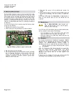
Page 6: ... jumper 6 Reconnect the power The service LED will blink twice and become solid indicating that the controller is application less The proper APB using the Commission or Load option in LNS e g SLX Series LMT can now be loaded into the controller 13 Maintenance Due to HIGH VOLTAGE direct contact will cause electrical shock or burn Turn off power before any kind of servicing The PFCU and PTU control...

Page 7: ...Page 7 of 8 15 Typical Fan Coil Application Wiring Diagram 4A Fast acting high breaking 5 x 20mm Fuse PART 216 004XP Littelfuse Fuse holder PART 3004100 Phoenix Contact 15A Fast acting high breaking 6 x 32mm Fuse PART 314015P Littelfuse Fuse holder PART 3004171 Phoenix Contact ...

Page 8: ...etwork termination Check the termination s Incorrect or broken termination s will make the communication integrity dependent upon a controller s position on the network Extra capacitance Make sure that no extra capacitance is being connected to the network other than the standard FTT circuit and a maximum of a 3 meter stub in bus topology Number of controllers on network segment exceeded The numbe...

Reviews: