Product Release Letter (English)
©SIEMENS A&D SE
24.01.2003
(ES4/Ka/WW8.0/A4)
C8451-A6-A83-4-7418
1
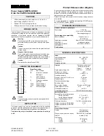
Power Supply SMP16-SV430
Order No: 6AR1306-0DC00-0AA0
FEATURES
•
Offline power supply unit with output for +15 V and –15 V
•
Input voltage range 94 to 264 V AC
•
Softstart: No U
a
overswing at switch-on
•
Slide-in module for 19-inch subrack (for individual locking)
WARNING NOTES
Trouble-free and safe operation of the unit is dependent on proper
transport and storage, as well as installation by qualified personnel.
Installation of the device requires that the applicable DIN/VDE
regulations or the safety regulations of your country be adhered to.
Warning
Protective ground (PE) must be connected with the
protective conductor of the power network of the power
company.
Caution
The device may only be used within the permitted input
voltage range.
Danger of electric shock
Since certain parts of electrical devices inevitably carry
dangerous voltage when these devices are operated,
incorrect handling of these devices may cause death or
serious injury as well as substantial property damage.
Caution
Electrostatic Sensitive Device (ESD)
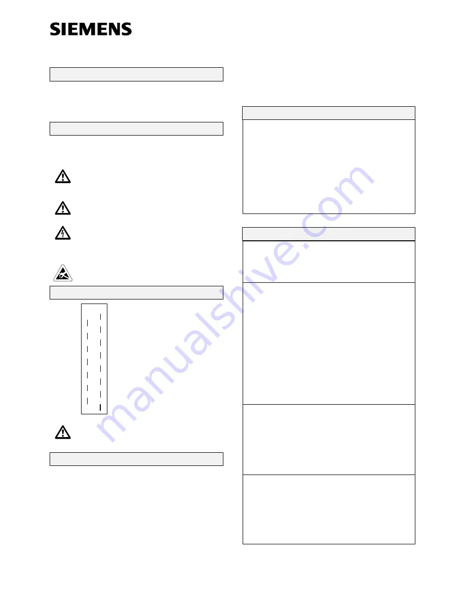
CONNECTOR ASSIGNMENT
4
6
8
10
12
14
16
18
20
22
24
26
28
30
32
L
PE
1)
N
2)
2)
1)
-15VL
0VL
0VL
1)
+15VL
1)
1)
1)
Signal Description
L, N
Input voltage
PE
protective conductor,
leading pin
1)
Used internally.
Do not connect.
2)
Protective conductor
potential
+15VL
Output voltage 1
–15VL
Output voltage 2
0VL
GND for outputs
Caution
The counter plug connector must be equipped with tin-
plated contacts.
INSTALLATION
The power supply may only be mounted and wired by qualified
personnel who are familiar with and observe the general rules of
this technology and the applicable regulations and standards.
This board may only be installed or removed when the voltage
is off.
To ensure proper ventilation, the device must be mounted vertically
so that the ventilation slits are pointing up or down. A free space of
at least 5 cm must be provided both above and below the device so
that convection is not obstructed.
Parallel circuiting of the outputs of several power supply boards is
not permitted.
For more information on installing and handling SICOMP boards,
see SICOMP IMC System Manual.
STANDARDS/CERTIFICATIONS
Galvanic isolation input/outputs
Test voltage
2.5 kV AC
SELV in acc. w. EN 60950
Overvoltage category II
Electromagnetic compatibility
Power feedback
Class A in acc. w.
EN 61000-3-2
Interference emission
(EN 50081-1)
Class B in acc. w. EN 55022
in reference system
Interference immunity
(EN 50082-2)
EN 61000-4-2/3/4/5/11
Certifications
CE
TECHNICAL SPECIFICATIONS
Input
Input voltage range
94 ... 264 V AC
Input frequency
50/60 Hz
Efficiency
η
80%
Operation indicator
LED
Outputs
Continuous short circuit
protected, idle-proof
Rated output voltage U
AN
Output 1
+15 V DC
Output 2
–15 V DC
Tolerance on delivery
±5%
Temperature coefficient
≤
0.025% / K
Deviation, dynamic:
±0.2%
Recovery time for 0.2 to 0.8 x I
AN
<
0.5 msec
Residual ripple:
<
20 mV
ss
Total interference voltage
<
50 mV
ss
Switch-on delay
1 s
Power failure bypass
40 msec at 100% load
Rated output current I
AN
1.5 A
1.5 A
Overload protection at:
ca. 2.2 A
Overvoltage protection
125% ±5% automatic return
Ambient conditions
Permissible ambient temperature
- during operation:
- during transport/storage:
0 °C to +55 °C
–25 °C to +85 °C
Power reduction above 50 °C
2.5% / K
Relative air humidity:
5 to 90%, no condensation
Degree of protection (EN 60529)
IP 20
Degree of protection (VDE 0106
Part 1)
I
General Specifications
Design:
19" plug-in unit,
individual locking
Plug connector (male connector):
DIN 41612-H15, tin plated
Weight:
approx. 0.5 kg
Dimensions:
- Width
- Height
- Length
8 TE (2 slots)
3 HE
160 mm


