7PG2113/4/5/6 Performance Specification
©2010 Siemens Protection Devices Limited
Chapter 3 Page 29 of 42
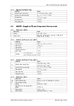
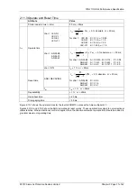
2.10.3 Operate and Reset Time
Attribute
Value
Starter operate time (
≥
2
xIs
) 20
ms,
±
20ms
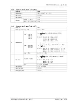
char
= IEC-NI,
IEC-VI,
IEC-EI,
IEC-LTI
[ ]
Tm
K
t
Is
I
op
×
−
=
1
α
,
±
5 % absolute or
±
30 ms,
for char = IEC-NI : K = 0.14,
α
= 0.02
IEC-VI : K = 13.5,
α
= 1.0
IEC-EI : K = 80.0,
α
= 2.0
IEC-LTI : K = 120.0,
α
= 1.0
char
= ANSI-MI,
ANSI-VI,
ANSI-EI
[ ]
Tm
B
A
t
P
Is
I
op
×
⎥
⎥
⎦
⎤
⎢
⎢
⎣
⎡
+
−
=
1
,
±
5 % absolute or
±
30 ms,
for char = ANSI-MI : A = 0.0515, B = 0.114, P = 0.02
ANSI-VI : A = 19.61, B = 0.491, P = 2.0
ANSI-EI : A = 28.2,
B = 0.1217, P = 2.0
t
op
Operate time
char
= DTL
t
d
,
±
1 % or
±
20ms
ANSI DECAYING
[ ]
Tm
R
t
Is
I
res
×
−
=
1
2
,
±
5 % absolute or
±
30 ms,
for char = ANSI-MI : R = 4.85
ANSI-VI : R = 21.6
ANSI-EI : R = 29.1
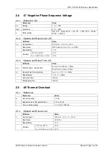
Reset time
t
res
t
res
,
±
1 % or
±
20ms
Repeatability
±
1 % or
±
20ms
Overshoot time
< 40 ms
Disengaging time
< 50 ms
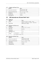
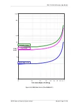
Figure shows the operate times for the four IEC IDMTL curves with a time multiplier of 1.
Figures 2.10-2 and 2.10-3 show the ANSI operate and reset curves. These operate times apply to non-directional
characteristics. Where directional control is applied then the directional element operate time should be added to
give total maximum operating time.


