7PG2113/4/5/6 Solkor Description of Operation
2.2
Case
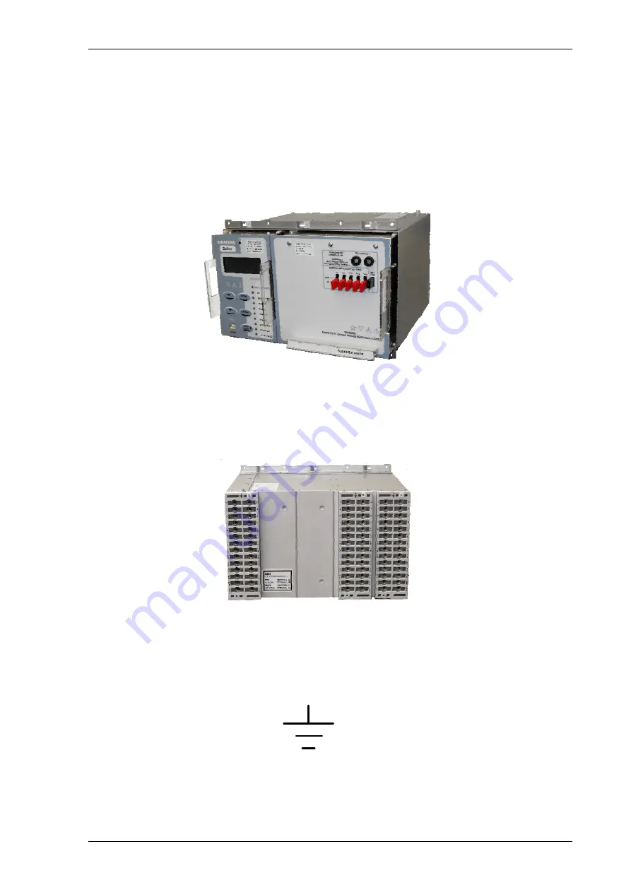
The relays are housed in cases designed to fit directly into standard panel racks. The case has a width of 260mm
and a height of 177 mm (4U). The required panel depth (with wiring clearance) is 242 mm.
The relay modules are withdrawable from the front of the case. Contacts in the case ensure that the CT circuits
and normally closed contacts remain short-circuited when the relay is removed. To withdraw the relay modules
remove the front cover by rotating the six securing pins and withdraw using the module handles. The relay
modules should not be carried using these handles..
Figure 2.2-1 Relay shown withdrawn
The rear terminal blocks comprise M4 female terminals for wire connections. Each terminal can accept two 4mm
crimps.
Figure 2.2-2 Rear view of 7PG2113/4/5/6 Relay
Located at the top rear of the case is a screw clamp earthing point, this must be connected to terminal B28 and
directly to the main panel earth. This connection point is indicated by the following symbol.
Figure 2.2-3 Earth Symbol
©2010 Siemens Protection Devices Limited Chapter 1 Page 16 of 80


