7PG2113/4/5/6 Installation Guide
3.2
Fixings
3.2.1 Epsilon
Cases
3.2.1.1 Wiring
Terminations
M4 Ring tongued crimps with 90
˚
bend are recommended.
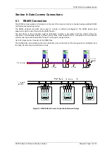
RS485 (Block ”B” Terms 14, 16, 18, 20) connection to this communication facility is by screened, twisted pair
cable. On site when wiring other facilities ensure that these terminals are not obscured by other wiring runs.
Cable should be RS485 compliant.
3.2.1.2 Panel
Fixings
Typical mounting screw kit per Relay
Consists of 4 off M4x10mm Screws
4 off M4 Nuts
4 off M4 Lock Washer
Typical rear terminal block fixing kit (1kit per terminal block fitted to relay) Consists of:
28 off M4, 8mm Screws
28 off M4 Lock Washer
3.2.2 Vedette
Cases
3.2.2.1 Wiring
Terminations
M5 Ring tongued crimps are recommended.
3.2.2.2
Panel Fixing
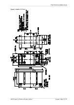
Vedette case mounting arrangement is shown in Figure 4.
3.2.3 Back of Panel cases
3.2.3.1 Wiring
Terminations
M6 Ring tongued crimps are recommended.
3.2.3.2 Mounting
arrangement
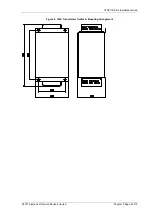
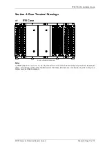
Case mounting arrangement is shown in Figure 5 & 6
©2010 Siemens Protection Devices Limited
Chapter 5 Page 9 of 15

