7PG2113/4/5/6 Commissioning & Maintenance
©2012 Siemens Protection Devices Limited
Chapter 6 Page 8 of 77
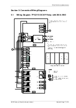
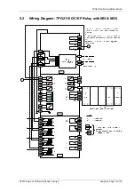
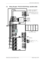
Ensure that the correct auxiliary supply voltage and polarity is applied. See the relevant scheme diagrams for the
relay connections.
Check that the nominal secondary current rating of the current and voltage transformers has been correctly set in
the System Config. menu of the relay.
1.2.6 Inspection
Ensure that all connections are tight and correct to the relay wiring diagram and the scheme diagram. Record any
deviations. Check that the relay is correctly programmed and that it is fully inserted into the case. Refer to
‘Section 2: Settings and Instruments’ for information on programming the relay.
1.2.7 Applying
Settings
The relay settings for the particular application should be applied before any secondary testing occurs. If they are
not available then the relay has default settings that can be used for pre-commissioning tests. See the Relay
Settings section of this manual for the default settings.
Note that the tripping and alarm contacts for any function must be programmed correctly before any scheme tests
are carried out.
Relays feature multiple settings groups, only one of which is active at a time. In applications where more than one
settings group is to be used it may be necessary to test the relay in more than one configuration.
Note.
One group may be used as a ‘Test’ group to hold test-only settings that can be used for regular
maintenance testing, eliminating the need for the Test Engineer to interfere with the actual in-service settings in
the normally active group. This Test group may also be used for functional testing where it is necessary to disable
or change settings to facilitate testing.
When using settings groups it is important to remember that the relay need not necessarily be operating
according to the settings that are currently being displayed. There is an ‘active settings group’ on which the relay
operates and an ‘edit/view settings group’ which is visible on the display and which can be altered. This allows the
settings in one group to be altered from the relay fascia while the protection continues to operate on a different
unaffected group. The ‘Active Settings Group’ and the ‘Edit Settings Group’ are selected in the ‘System
Configuration Menu’.
The currently Active Group and the group currently Viewed are shown at the top of the display in the Settings
display screen. If the View Group is not shown at the top of the display, this indicates that the setting is common
to all groups. CT/VT ratio, I/O mapping and other settings which are directly related to hardware are common to
all groups.
If the relay is allowed to trip during testing then the instruments display will be interrupted and replaced by the
‘Trip Alert’ screen which displays fault data information. If this normal operation interferes with testing then this
function can be temporarily disabled for the duration of testing by use of the Trip Alert Enabled/Disabled setting in
the System Config Menu.
After applying a settings change to the relay, which may involve a change to the indication and output contacts,
the
TEST/RESET
key should be pressed to ensure any existing indication and output is correctly cleared.
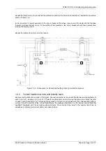
Where 15kV Pilot isolating transformers are used the terminals connected to the pilots should be carefully
checked to ensure that the same tap is used at each end. The protection should normally be connected on the N
tapping. The N1 tapping should only be used where very low settings are required (e.g. in non-effectively earthed
systems), and because of its greater sensitivity, care is necessary in the choice of current-transformers. It should
be noted that the N1 tapping is not brought out to a terminal on the relay backplate, and if it is to be used the lead
which is normally connected to the terminal N on top of the summation transformer should be connected to the
adjacent N1 terminal on the internal terminal block.
1.3
Tests
1.3.1 Secondary Injection Tests
Select the required relay configuration and settings for the application.
Isolate the auxiliary D.C. supplies for alarm and tripping from the relay and remove the trip and intertrip links.
Carry out injection tests for each relay function, as described in this document

