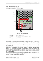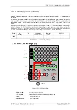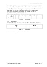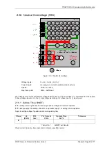
7PG2113/4/5/6 Commissioning & Maintenance
©2012 Siemens Protection Devices Limited
Chapter 6 Page 59 of 77
2.16.2 Inverse Time (59NIT)
It will be advantageous to map the function being tested to temporarily drive the relevant Pickup output in the
Pickup Config
sub-menu in the
Output Config
menu as this will allow the Pick-up led to operate for the function.
Gradually increase voltage until Pickup LED operates.
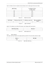
Apply 2x setting voltage and record operating time,
Apply a higher multiple of setting voltage and record operating time.
Compare to calculated values for operating times from:
( )
[ ]
⎥
⎦
⎤
⎢
⎣
⎡
−
=
1
1
sec
Vs
Vn
op
M
t
Where M = Time multiplier and Vn/Vs = multiple of setting.
Operate Voltage
Operate Time
Ph. Vs
(V)
TM
P.U.
(Volts)
D.O.
(Volts)
Tol
2 x Vs
(sec)
x Vs
(sec)
Tol
P.U.
D.O.
&
TIMING
TESTS
E
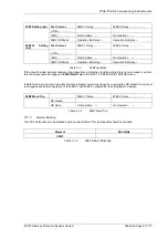
Table 2.16-2
59NIT Test Results
2.16.2.1 Element
Blocking
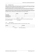
The Neutral Overvoltage elements can be blocked by Binary Input Inhibit. This functionality should be checked.
Element BI
Inhibits
59NIT
59NDT
Table 2.16-3
59N Element Blocking
Check correct indication, trip output, alarm contacts, waveform record.
When testing is complete reinstate any of the disabled functions.


