7PG2113/4/5/6 Commissioning & Maintenance
©2012 Siemens Protection Devices Limited
Chapter 6 Page 62 of 77
3.2
Voltage Transformer Supervision (60VTS)
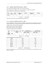
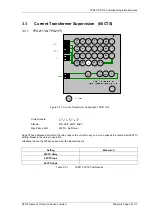
Figure 3.2-1 Voltage Transformer Supervision
Voltage Inputs:
V
L1
(V
A
), V
L2
(V
B
), V
L3
(V
C
)
Current Inputs:
I
L1
(I
A
), I
L2
(I
B
), I
L3
(I
C
),
Disable:
27,
47,
59N
Map Pickup LED:
60VTS - Self Reset
3.2.1 1 or 2 Phase VT fail
Apply 3P balanced nominal current and voltage. Reduce 1 phase voltage until VTS operates, record voltage
reduction level.
60VTS V Setting
Setting x 3
Measured Voltage Reduction
Table 3.2-1
60VTS Voltage Setting
increase the voltage until VTS resets. Increase current on 1 phase by 110% of 3x the
60VTS I
setting. Reduce
voltage as above and check for no operation. Return voltage to nominal. Increase current on 1 phase by 90% of
3x the
60VTS I
setting. Reduce voltage as above and check for VTS operation
Table 3.2-2
60VTS Current Setting
60VTS I Setting
Setting x 3
110% of Setting x 3
90% of Setting x 3
No VTS
□
VTS
operation
□

