7PG2113/4/5/6 Solkor Description of Operation
3.2
Operation
Solkor R belongs to the circulating current class of differential protections which can be recognised by two main
features. Firstly, the current-transformer secondaries are arranged to produce a current circulating around the
pilot loop under external fault conditions. Secondly, the protective relay operating coils are connected in shunt
with the pilots across points which have the same potential when the current circulates around the pilot loop. In
this particular scheme equipotential relaying points during external fault conditions exist at one end during one
half cycle of fault current, and at the other end during the next half cycle. During half cycles when the relay at
either end is not at the electrical midpoint of the pilot system the voltage appearing across the relay is in the
reverse direction to that required for operation.
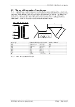
At each end of the feeder the secondaries of the current transformers are connected to the primary of the
summation transformer – see section 3.3 Theory of Summation Transformer. For various types of current
distribution in the three current transformers, a single phase quantity appears in the summation transformer
secondary winding and is applied to the pilot circuit. By this means a comparison between the currents at each
end of a three phase line is effected over a single pair of pilot wires on an equivalent single phase basis. The
tappings on the summation transformer primary have been selected to give an optimum balance between the
demands of fault setting and stability.
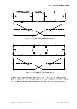
The pilot is shown as a ‘lumped’ resistor R
P
. The rest of the pilot loop is made up of four resistors R
a
and four
diodes D1, D2, D5 and D6. The operating elements, which are made unidirectional by diodes D3, D4, D7 and D8
are connected in shunt with the pilots.
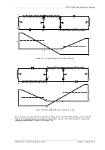
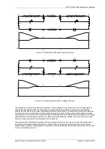
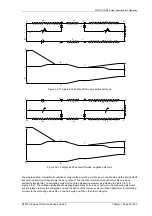
During an external fault condition, an alternating current circulates around the pilot loop. Thus on successive half
cycles one or other of the resistors R
a
at the two ends of the pilot is short circuited by its associated diode D1 or
D2. The total resistance in each leg of the pilot loop at any instant is therefore substantially constant and equal to
R
a
+R
p
. The effective position of R
a
however, alternates between ends, being dependent upon the direction of the
current. The change in the effective position of R
a
makes the voltage distribution between the pilot cores different
for successive half-cycles of the pilot current.
In other words stability is achieved by current balance using the Solkor R principle of establishing the electrical
centre point geographically within the end which has positive polarity so that the positively polarised measuring
elements remain in the negative part of the circuit and are thus biased against operation.
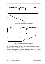
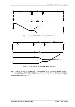
Referring to the basic circuit of Solkor Rf as shown in Figure 3.1-2, the circulating current will flow from the
summation transformer through the diode or the resistor depending on the polarity of the summation transformer
output. Thus the circuit may be redrawn to suit the polarities of summation transformer output as shown in Figure
3.2-1 & Figure 3.2-2 below.
©2010 Siemens Protection Devices Limited Chapter 1 Page 27 of 80


