PROFIBUS Interface Center
SPC3
Page 56
V1.3
SPC3 Hardware Description
2003/04
Copyright (C) Siemens AG 2003. All rights reserved.
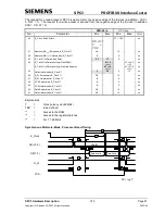
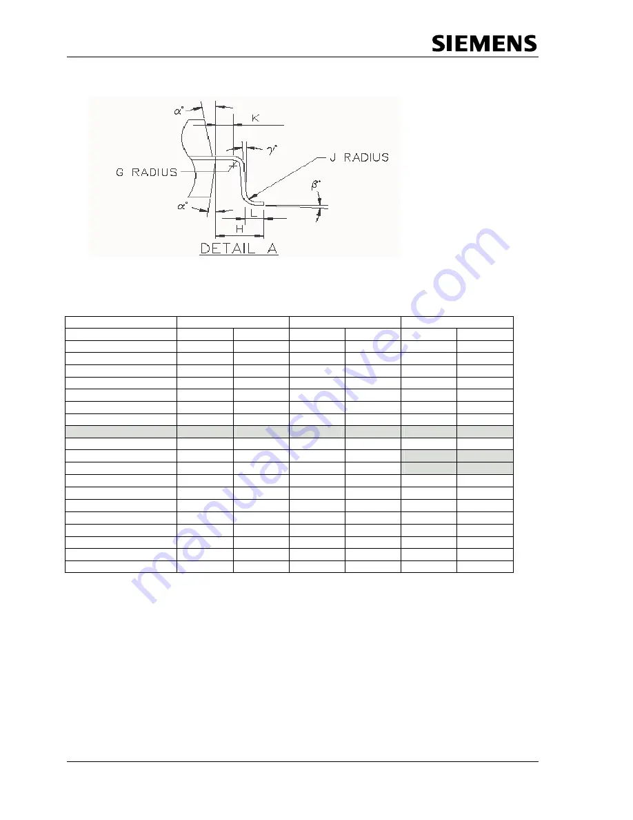
Symbol
Min
Typ
Max
AMI-Vers.
ST-Vers.
AMI-Vers.
ST-Vers.
AMI-Vers.
ST-Vers.
A
-
-
2.13
-
2.35
2.45
A1
0.10
0.25
0.15
-
0.25
-
A2
1.95
1.90
2.00
2.00
2.10
2.10
D
13.65
13.65
13.90
13.90
14.15
14.15
D1
9.90
9.90
10.00
10.00
10.10
10.10
E
13.65
13.65
13.90
13.90
14.15
14.15
E1
9.90
9.90
10.00
10.00
10.10
10.10
L
0.65
0.78
0.80
0.88
0.95
1.03
e BASIC
-
-
0.80
0.80
-
-
B
0.30
0.30
-
0.35
0.45
0.40
c
0.13
-
-
-
0.23
0.17
α
αα
α
°
12
-
-
10
16
-
ββββ
°
0
0
-
-
7
7
γγγγ
°
0
1
-
5
-
9
G
0.13
-
-
0.20
-
-
H
-
-
1.95
-
-
-
J
-
-
0.30
0.30
-
-
K
0.40
-
-
-
-
-
2H (Footprint)
-
-
3.90
3.90
-
-
8.5.8 Processing Instructions
ESD protective measures must be maintained for all electronic components.
SPC3 is a cracking-endangered component that must be handled as such.
A drying process must be carried out before SPC3 is processed. The component must be dried at 125o C
for 24 hours and then be processed within 48 hours. This drying process may be carried out once only
because the component is soldered.
It must also be ensured that the SPC3’s connections are not bent. Flawless processing can be guaranteed
only if a planity of less than 0.1 mm is ensured. SPC3 is released for infrared soldering with a soldering
profile according to CECC00802.
Summary of Contents for SPC3
Page 1: ...SIMATIC NET SPC3 Siemens PROFIBUS Controller Hardware Description Date 2003 04 09 ...
Page 2: ......
Page 67: ......


