background image

10/26 

Building Technologies Division 


CC1N7817en 


24.02.2015 

Type summary 

(cont´d) (other types on request) (cont’d)


Note 
Not all types of actuators are available ex stock. Additional versions are available on 
request. 


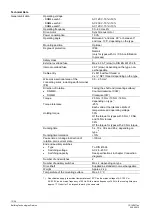
Type of drive shaft 

Max. 

torque 

Shaft 

no. 

 10 mm

, woodruff key as per DIN 6888 

10 Nm 

 9.5 mm

, square shaft


15 Nm 

 10 mm 

D type shaft, compatible with SQM45...


10 Nm 

 14 mm

 with parallel key as per DIN 6885, compatible with SQM48...


20 Nm 

Drive shafts: 

Summary of Contents for SQM40 Series

Page 1: ...as well as GL marine approval The SQM40 SQM41 and this Data Sheet are intended for use by OEMs which integrate the actuators in their products Use The SQM40 SQM41 actuators are suited for driving oil pressure controller butterfly valves dampers or for use on other applications that require rotary motion Areas of application are oil and gas burners of medium to higher capacity as well as thermal pr...

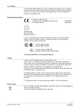
Page 2: ...ted from power The electrical connection between the conduit fittings is not made automatically It must be established on installation site The connecting plate is made of plastic and does not provide earthing of the conduit fittings Earthing must be ensured by adequate washers and wire links All cam switch settings must satisfy the requirements of the relevant application standards To provide pro...

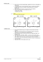
Page 3: ...W SQM41 right CW 0 1 3 5 0 1 3 5 90 90 Installation notes Ensure that the electrical wiring is in compliance with national and local safety regulation Make certain that strain relief of the connected cables conforms to the relevant standards e g as per DIN EN 60730 and DIN EN 60335 Ensure that spliced wires cannot get into contact with neighboring terminals Use adequate ferrules Unused terminals o...

Page 4: ...used output terminals see chapter Connection diagrams For this purpose specific unit variants are available fitted with a unit internal non replaceable fuse The unit internal fuse is used to protect each switching contact from welding in the event of external short circuit In addition please note that the maximum current load for the fused output terminals is reduced see chapter Connection diagram...

Page 5: ...lications environmental category A Lifetime The actuator has a designed lifetime of 250 000 start cycles close open close under load with the rated torque in the entire rotation angle range which under normal operating conditions in heating mode corresponds to approx 10 years of usage starting from the date of manufacture on the device type plate This lifetime is based on the endurance tests speci...

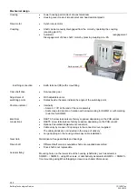
Page 6: ...M40 RAST3 5 screw terminals are factory supplied depending on the PCB variant RAST5 screw terminals are factory supplied depending on the PCB variant Optional Insulation displacement connectors Cable entry by means of 2 openings in the connector cover supplied The cable glands are not included in the scope of delivery Large openings in the housing allow easy cable installation Maintenance free gea...

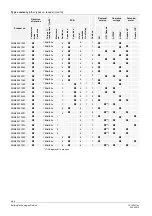
Page 7: ...QM40 155R11 5Nm 15s 5 4 5 SQM40 155R13 5Nm 15s 5 4 5 SQM40 161A20 5Nm 15s 6 6 1 SQM40 164R11 5Nm 15s 6 6 4 SQM40 165A20 5Nm 15s 6 6 5 SQM40 165A21 5Nm 15s 6 6 5 SQM40 165R11 5Nm 15s 6 6 5 SQM40 171A20 5Nm 15s 7 5 1 1 SQM40 174R10 5Nm 15s 7 5 1 4 SQM40 175A21 5Nm 15s 7 5 1 5 SQM40 185R11 5Nm 15s 8 6 5 SQM40 215R11 10Nm 30s 1 3 5 SQM40 215R13 10Nm 30s 1 3 5 SQM40 235A20 10Nm 30s 3 4 3 5 SQM40 241A11...

Page 8: ...21 10Nm 30s 6 6 4 SQM40 264R11 10Nm 30s 6 6 4 SQM40 265A11 10Nm 30s 6 6 5 SQM40 265A20 10Nm 30s 6 6 5 SQM40 265A21 10Nm 30s 6 6 5 SQM40 265R11 10Nm 30s 6 6 5 SQM40 267A20 10Nm 30s 6 6 7 SQM40 271A20 10Nm 30s 7 5 1 1 SQM40 271R10 10Nm 30s 7 5 1 1 SQM40 274R10 10Nm 30s 7 5 1 4 SQM40 275A20 10Nm 30s 7 5 1 5 SQM40 275A21 10Nm 30s 7 5 1 5 SQM40 275R10 10Nm 30s 7 5 1 5 SQM40 281A20 10Nm 30s 8 6 1 SQM40 ...

Page 9: ...10Nm 30s 4 3 1 SQM41 244A21 10Nm 30s 4 3 4 SQM41 244R11 10Nm 30s 4 3 4 SQM41 245A11 10Nm 30s 4 3 5 SQM41 245A21 10Nm 30s 4 3 5 SQM41 245R11 10Nm 30s 4 3 5 SQM41 254R11 10Nm 30s 5 4 4 SQM41 261A11 10Nm 30s 6 6 1 SQM41 261A21 10Nm 30s 6 6 1 SQM41 261R11 10Nm 30s 6 6 1 SQM41 264A21 10Nm 30s 6 6 4 SQM41 264R11 10Nm 30s 6 6 4 SQM41 265R11 10Nm 30s 6 6 5 SQM41 267A21 10Nm 30s 6 6 7 SQM41 271R10 10Nm 30s...

Page 10: ...es of actuators are available ex stock Additional versions are available on request Type of drive shaft Max torque Shaft no 10 mm woodruff key as per DIN 6888 10 Nm 1 9 5 mm square shaft 15 Nm 4 10 mm D type shaft compatible with SQM45 10 Nm 5 14 mm with parallel key as per DIN 6885 compatible with SQM48 20 Nm 7 Drive shafts ...

Page 11: ...45 version is factory prefitted onto the SQM40 SQM41 Connector sets on request With screw terminals for replacement For SQM4x x1xxxx AGA45 1 For SQM4x x4xxxx AGA45 4 For SQM4x x2xxxx SQM4x x5xxxx AGA45 5 For SQM4x x3xxxx SQM4x x6xxxx SQM4x x7xxxx SQM4x x8xxxx AGA45 6 Potentiometers on request For retrofitting For SQM40 SQM41 Double potentiometer 2 1000 90 ASZ22 32 For SQM40 Double potentiometer 2 ...

Page 12: ...lockwise CCW SQM41 Clockwise CW Torque 2 5 Nm 5 Nm 10 Nm 18 Nm depending on type 1 Torque tolerance 25 Each valid at the tolerance limits of temperature and operating voltage Holding torque 50 Of the torque for types with 5 Nm 10 Nm and 18 Nm torque 36 Of the torque for types with 2 5 Nm torque Running time 5 s 15 s 30 s and 65 s depending on type 1 Running time tolerance 10 Pause time at change i...

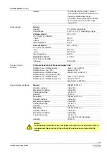
Page 13: ... SQM4x x5xxxx X2 PE SQM4x x6xxxx SQM4x x7xxxx SQM4x x8xxxx X1 X2 X3 PE Class 1 min AWG 16 Suited for 105 C Max 2 5 mm or AWG 14 SQM4x x1xxxx SQM4x x2xxxx SQM4x x4xxxx SQM4x x5xxxx X1 Class 2 min AWG 22 Suited for 105 C Max 1 mm or AWG 18 Storage DIN EN 60721 3 1 Climatic conditions Class 1K3 Mechanical conditions Class 1M2 Temperature range 20 60 C Humidity 95 r h Transport DIN EN 60721 3 2 Climat...

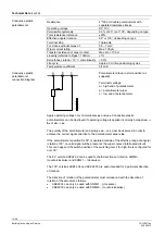
Page 14: ...ic potentiometers can be destroyed if operating voltage is applied incorrectly between a b or b c The polarity of the potentiometer end pickups a c must be observed in order to achieve the correct signal direction to the potentiometer wiper b If the potentiometer specified for 90 is operated outside of the effective range of angular rotation of 90 no valid signal will be present at the wiper conta...

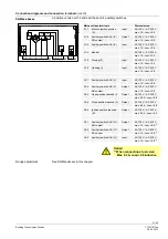
Page 15: ...30 V max 60 mA 30 mA X2 6 Neutral Input AC 120 V AC 230 V max 60 mA 30 mA X2 7 Open position reached I Output AC 120 V AC 230 V max 10 mA cos 0 9 Mains voltage terminals Dimensioning X2 1 Open I Input AC 120 V AC 230 V max 1 A cos 0 9 X2 2 Move to low fire V Input AC 120 V AC 230 V max 1 A cos 0 9 X2 3 Low fire position reached V Output AC 120 V AC 230 V max 10 mA cos 0 9 X2 4 Close ignition VI In...

Page 16: ... NO contact Output AC 120 V AC 230 V max 1 A cos 0 9 X2 4 Auxiliary switch AUX IV Input AC 120 V AC 230 V max 1 A cos 0 9 X2 5 Auxiliary switch AUX IV NC opener Output AC 120 V AC 230 V max 1 A cos 0 9 X2 6 Low fire position ignition load position reached V VI Output AC 120 V AC 230 V max 10 mA cos 0 9 X2 7 Close ignition VI Input AC 120 V AC 230 V max 1 A cos 0 9 X2 8 Neutral Input AC 120 V AC 23...

Page 17: ...ut AC 120 V AC 230 V max 1 A cos 0 9 X1 6 Auxiliary switch AUX VI NC opener Output AC 120 V AC 230 V max 1 A cos 0 9 X2 1 Fan supply voltage Input AC 120 V AC 230 V max 1 A cos 0 9 X2 2 Mains voltage close Input AC 120 V AC 230 V max 1 A cos 0 9 X2 3 Low fire controller Input AC 120 V AC 230 V max 1 A cos 0 9 X2 4 Fan motor Output AC 120 V AC 230 V max 1 A cos 0 9 X2 5 Free X3 1 Auxiliary switch A...

Page 18: ...not permitted to connect additional external loads such as signal lamps Adjust the range of the analog signal to match the switch positions min and max position 1 Set cam I to the required high fire position e g 85 position is indicated on the scale next to the cam 2 Set cam V to the required low fire position e g 20 3 Preset the signal at the analog input according to the required high fire posit...

Page 19: ...iometer low fire Note When starting up the direction of rotation of the potentiometer setting must be observed 7817z10 0713 Max Min 90 135 0 Note The working range of the potentiometer setting shown as an example for the current input 4 20 mA Setpoint I mA 20 18 16 14 12 10 8 6 4 2 0 min 0 max 90 135 V I 10 20 30 40 50 60 70 80 90 Positioning angle 7817d04e 0315 30 60 90 120 135 ...

Page 20: ...120 V AC 230 V max 1 A cos 0 9 X2 4 Auxiliary switch AUX IV Input AC 120 V AC 230 V max 1 A cos 0 9 X2 5 Auxiliary switch AUX IV NC opener Output AC 120 V AC 230 V max 1 A cos 0 9 X2 6 Low fire position ignition load position reached V VI Output AC 120 V AC 230 V max 10 mA cos 0 9 X2 7 Close ignition VI Input AC 120 V AC 230 V max 1 A cos 0 9 X2 8 Neutral Input AC 120 V AC 230 V max 60 mA 30 mA X2...

Page 21: ... max 1 A cos 0 9 X1 6 Opening I Input AC 120 V AC 230 V max 1 A cos 0 9 X2 1 Auxiliary switch AUX V Input AC 120 V AC 230 V max 1 A cos 0 9 X2 2 Auxiliary switch AUX V NO contact Output AC 120 V AC 230 V max 1 A cos 0 9 X2 3 Open position reached I Output AC 120 V AC 230 V max 0 3 A cos 0 8 X2 4 Close position reached II Output AC 120 V AC 230 V max 0 3 A cos 0 8 X2 5 Ignition position reached III...

Page 22: ...ut AC 120 V AC 230 V max 1 A cos 0 9 X1 6 Opening I Input AC 120 V AC 230 V max 1 A cos 0 9 X2 1 Mains voltage Input AC 120 V AC 230 V max 1 A cos 0 9 X2 2 Open close relay Input AC 120 V AC 230 V max 1 A cos 0 9 X2 3 Open position reached I Output AC 120 V AC 230 V max 0 3 A cos 0 8 X2 4 Close position reached II Output AC 120 V AC 230 V max 0 3 A cos 0 8 X2 5 Ignition position reached III Output...

Page 23: ...max 1 A cos 0 9 X1 6 Opening I Input AC 120 V AC 230 V max 1 A cos 0 9 X2 1 Auxiliary switch AUX V Input AC 120 V AC 230 V max 1 A cos 0 9 X2 2 Auxiliary switch AUX V NO contact Input AC 120 V AC 230 V max 1 A cos 0 9 X2 3 Position reached I II III Output AC 120 V AC 230 V max 0 3 A cos 0 8 X2 4 Auxiliary switch AUX IV NC opener Output AC 120 V AC 230 V max 1 A cos 0 9 X2 5 Auxiliary switch AUX V ...

Page 24: ...am Color Position Preadjustment Cam I Red High fire 90 Cam II Blue Not used Cam III Orange Not used Cam IV Yellow Not used Cam V Black Low fire 15 Cam VI Green OFF ignition 0 2 position version Cam Color Position Preadjustment Cam I Red High fire 90 Cam II Blue OFF low fire 0 Cam III Orange Ignition position 15 Cam IV Yellow Not used Cam V Black Not used Cam VI Green Auxiliary switch 30 Electronic...

Page 25: ...OFF low fire 0 Cam III Orange Ignition position 15 Cam IV Yellow Auxiliary switch 30 Cam V Black Auxiliary switch 30 Cam VI Green Auxiliary switch 30 3 position version Cam Color Position Preadjustment Cam I Red High fire 90 Cam II Blue OFF low fire 0 Cam III Orange Ignition position 15 Cam IV Yellow Auxiliary switch 30 Cam V Black Not used Cam VI Green Auxiliary switch 30 SQM4x x6xxxx SQM4x x8xxx...

Page 26: ...N6885 T3 SQM4x xxxRxxx connecting cover Shaft no 5 deep Slot for woodruff key 3x3 7 series A Din6888 4 through holes for screws M5 SQM4x xx1xxx SQM4x xx4xxx SQM4x xx5xxx SQM4x xx7xxx 1 4 5 7 7817m01e 0312 3 blind holes 10 mm deep for self tapping screws M5 SQM40 SQM41 2015 Siemens AG Building Technologies Division Berliner Ring 23 D 76437 Rastatt Subject to change ...

Reviews: