14/26
Building Technologies Division
CC1N7817en
24.02.2015
Technical Data
(cont´d)
Resistance 2*1000
double potentiometer with
separated resistance tracks
Operating voltage
DC 10 V
Permissible hysteresis
0.3% of 90° or of 135°, depending on type
Total resistance tolerance
±20%
Effective angular rotation
90° or 135°, depending on type
Terminal strip
Triple-pole
For cross-sectional areas of
0.5...1 mm²
Wiper current rating
Max. 100 µA
Transfer resistance of wiper contact
Max. Rü
100
Linearity (referred to Rges = 1000
)
1%
Smoothness (alpha = 10°) / microlinearity
<0.5%
Life cycle
Approx. 2 million positioning cycles
Temperature coefficient
0.4
/K
a
b
c
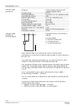
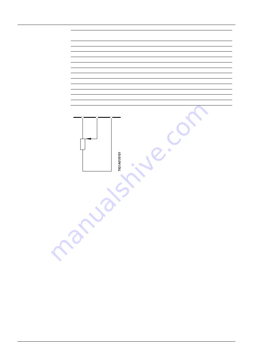
Potentiometer drawn in start position (as
supplied).
Terminal markings:
a = high end of potentiometer
b = potentiometer wiper
c = low end of potentiometer
Apply operating voltage only on terminals
«a»
and
«c»
. Conductive plastic
potentiometers can be destroyed if operating voltage is applied incorrectly between
«a
b»
or
«b
c»
.
The polarity of the potentiometer end pickups
«a
c»
must be observed in order to
achieve the correct signal direction to the potentiometer wiper
«b»
.
If the potentiometer specified for 90° is operated outside of the effective range of angular
rotation of 90°, no valid signal will be present at the wiper contact (interrupted circuit).
This can happen if the switch position of the switching cam
I
for high-fire is configured for
over 90°.
The 90° version ASZ22.32 can be used for both directions of rotation, SQM40...
(counterclockwise) and SQM41... (clockwise).
The 135° versions ASZ22.34 and ASZ22.35 are each intended for a particular direction
of rotation.
The direction of rotation of the potentiometer must correspond with the direction of
rotation of the actuator as follows:
ASZ22.34 can only be used with SQM41... (clockwise)
ASZ22.35 can only be used with SQM40... (counterclockwise)
Conductive plastic
potentiometer
Conductive plastic
potentiometer
connection diagram


