2/8
Siemens Building Technologies
CC1N7814en
HVAC Products
31.10.2002
Warning notes
To avoid injury to persons, damage to property or the environment, the following
warning notes should be observed!
Do not open, interfere with or modify the actuators!
·
Ensure protection against electric shock hazard by providing adequate protection
for the connection terminals
·
Check to ensure that wiring is in an orderly state and that the wires are firmly con-
nected
Mounting notes
·
Ensure that the relevant national safety regulations are complied with
·
The connection between actuator drive shaft and controlling element must be
rigid
with
no mechanical play
Possible connection with drive shaft or hub:
·
Groove with Woodruff key
·
Drive shaft with flat edge and matching counterpiece
To avoid inadmissible loads on bearings caused by rigid hubs, it is recommended to
use compensating clutches with no mechanical play (e.g. metal bellows clutches).
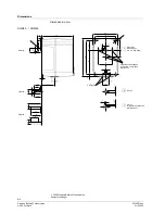
Only the specified cable may be used (refer to Basic Documentation P7550). The ca-
ble’s shielding must be connected to the printed circuit board using the tab provided.
Ensure that the actuator’s housing is connected to functional earth (FE) of the system.
If necessary, remove isolating layers of paint from the fixing points on the burner’s
casing or run separate earth wires.
For detailed information, refer to «Installation Inctructions for the LMV5x system»
J7550.1.
CAN bus
AGG5.6...
SQM4...
FE
Basic un
it
LMV5...
7814z
03
e/
0502
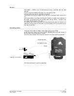
The working range is given on the type field and must be observed when mounting the
actuator. To ensure the actuator is accurately located on the burner, a positioning pin of
6 mm diameter must be fitted on the mounting surface.
Positive connection
Cable and cable
shielding
Working range of
actuator


