7/8
Siemens Building Technologies
CC1N7814en
HVAC Products
31.10.2002
Function
The SQM45... / SQM48... are of robust design and have a geartrain with only small
backlash.
Control and position feedback take place via a bus system (CAN).
The bus cable is also used for powering the actuators.
The actuators are driven by stepper motors and can be positioned with a resolution of
0.1°.
The characteristics and settings (running time, direction of rotation, limit positions) of
the SQM4... are determined by the controlling basic unit (e.g. LMV5...; for details, refer
to the Basic Documentation of the LMV...).
The running times of the associated controlling elements are varied by the basic unit
depending on the burner’s control phase (e.g. startup phase: short running time; opera-
tion: long running time).
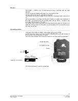
Terminating resistor
At the end of the serial bus cabling, a terminating resistor must be fitted.
For that purpose, a jumper must be set to BUS TERMINATION on the last actuator of
the bus cable, which will activate the resistor.
On all the other actuators, that jumper must be set to the other position (deactivated).
Addressing button
12
VA
C
1
12
VA
C
2
CA
N
H
CA
N
L
GN
D
X1
78
14z01
e/
1002
LED (function code)
Jumper
X2
Bus
termination
12
VA
C
1
12
VAC
2
CA
NH
CA
NL
GN
D
Assignment of terminals
The 2 terminal blocks (X1 and X2) are identical.


