SQM5… Reversing Actuators
Technical Instructions
Document No. 155-517P25
July 9, 2007
Siemens Building Technologies, Inc.
Page 13
AGA56.9… Circuit
Boards
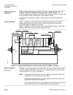
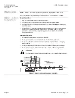
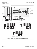
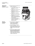
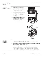
See Figures 11 and 12.
Manual Operation
1.
Set the AUTO/MAN switch in the MAN position.
2.
Connect ground to the screw located below the shaft release button.
3.
Connect neutral to terminal N.
4.
Only terminal "L" must be powered to enable manual operation. The actuator can
now be driven to the maximum (high fire) position (switch cam I) or the fully closed
"economy position" (switch cam II) by using the toggle switch located to the left of
the AUTO/MAN switch.
Automatic Operation
1. Set the AUTO/MAN switch in the AUTO position.
2. Connect ground to the screw located below the shaft release button.
3. Connect neutral to terminal N.
4. Connect line voltage at all times to terminal L to provide power to the electronic
circuit board.
5. Connect line voltage to terminal L1 to provide power when modulating. Connect line
voltage to terminal L1
only
after removing power on terminals A and Z (otherwise
actuator damage may result).
6. Connect line voltage to terminal A to drive the actuator to the maximum (high fire
purge) position. Once the maximum position is reached, terminal 11 (on switch I)
will be energized to provide position feedback.
7. Connect power to terminal ZL to drive the actuator to the minimum (low-fire)
position. Once the minimum position is reached, terminal 23 (on switch III) will be
energized to provide position feedback. Adjustment of switch III will determine the
low-fire stop position. Switch III (low fire) must be set at a higher position than
switch II (fully closed). Terminal ZL may be energized
only
after removing power
from terminals A, Z, 13, and LR.
8. Connect line voltage to terminal Z to drive the actuator to the fully closed/economy
position (switch II).
9. Connect the input control signal wires to the appropriate terminals. See Figure 11.
CAUTION:
Do not power terminals A and Z simultaneously. Actuator damage will
occur.

