Technical Instructions
SQM5… Reversing Actuators
Document No. 155-517P25
July 9, 2007
Page 16
Siemens Building Technologies, Inc.
Cover Installation
1.
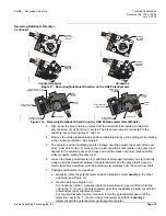
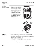
Lift the two screws on the cover corners and slide the cover end into the grooves
at the gear end of the actuator. See Figure 14.
2.
Press the cover into place and then press the screws inward and tighten. See
Figure 15.
EA0567R1
Figure 14.
EA0563R1
Figure 15.
Features of
SQM5x.xxxxxZx
Actuators
SQM5xx.xxxxx
Z
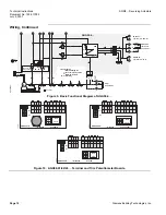
x actuators contain the AGA56.9A… multi function circuit board. This
circuit board provides the following features:
Multiple Input Signals
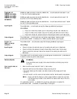
The AGA56.9A… circuit board accepts the following input signals:
Line voltage
•
Power to A drives the actuator open to the setting of switch cam I (Maximum).
•
Power to ZL drives the actuator closed to the setting of switch cam III (Minimum).
•
Power to Z drives the actuator closed to the setting of switch cam II (Economy).
•
4 to 20 mA
(Signal to Y3, common to M)
•
0 to 135
Ω
(Slide wire signal to Y0, potentiometer connected to M and U4)
•
0 to 10 Vdc
(Signal to Y1, common to M)
•
0 to 20 mA
(Signal to Y2, common to M)
Multiple Output Signals
The AGA56.9A… circuit board provides the following output signals:
•
4 to 20 mA
(Signal from U3, common to M)
•
0 to 10Vdc
(Signal from U1, common to M)
•
0 to 20mA
(Signal from U2, common to M)
Double potentiometers ASZ22… provide additional output signals.


