background image

Technical Instructions 

SQM5… Reversing Actuators 

Document No. 155-517P25 
July 9, 2007 
 

Page 4


Siemens Building Technologies, Inc. 


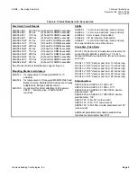
Product Numbers 

Table 1.  Product Numbers for Pre-assembled Actuators. 


Torque

1

Running 

Time 

[lb-in]

90°@ 60 

Hzsec

Lin

e


Voltag

e

4-

20 mA

0-1

35 

Ω

0

-10 V

d

c

110 V

220 V

24 V

90

8

ccw

x

x

SQM50.261R1G3

90

8

cw

x

x

SQM50.261R1G3R

90

8

ccw

x

SQM50.264R1A

SQM50.264R2A

90

8

cw

x

SQM50.264R1A0R

90

8

ccw

x

SQM50.264R1A3

90

8

cw

x

x

SQM50.264R1G3R

90

8

ccw

x

x

SQM50.264R1G4

140

12

ccw

x

x

SQM50.361R1G3

140

12

cw

x

x

SQM50.361R1G3R

140

12

ccw

x

x

SQM50.361R1G7

140

12

ccw

x

x

SQM50.364R1G3

140

12

cw

x

x

SQM50.364R1G3R

140

25

ccw

x

SQM50.461R1A

140

25

ccw

x

SQM50.461R1A3

140

25

ccw

x

x

SQM50.461R1G3

140

25

cw

x

x

SQM50.461R1G3R

140

25

ccw

x

x

SQM50.461R1H3

140

25

ccw

x

x

x

x

SQM50.461R1Z3

140

25

ccw

x

x

x

x

SQM50.461R1Z7

140

25

ccw

x

SQM50.464R1A

SQM50.464R8A

140

25

cw

x

SQM50.464R1A0R

140

25

ccw

x

SQM50.464R1A3

140

25

cw

x

SQM50.464R1A3R

140

25

ccw

x

x

SQM50.464R1G3

SQM50.464R8G3

140

25

cw

x

x

SQM50.464R1G3R

SQM50.464R2G3R 

140

25

ccw

x

x

SQM50.464R1G7

140

25

cw

x

x

SQM50.464R1G7R

140

25

ccw

x

x

SQM50.464R1H3

SQM50.464R8H3

140

25

ccw

x

x

x

x

SQM50.464R1Z3

SQM50.464R2Z3

SQM50.464R8Z3

200

25

ccw

x

SQM53.464R1A

200

25

ccw

x

SQM53.464R1A3

200

25

ccw

x

x

SQM53.464R1G3

200

25

ccw

x

x

SQM53.464R1G7

200

25

cw

x

x

SQM53.464R1G7R

200

25

ccw

x

x

x

x

SQM53.464R1Z3

SQM53.464R2Z3

200

25

ccw

x

x

x

x

SQM53.467R1Z3

200

25

cw

x

x

x

x

SQM53.467R1Z3R

200

25

ccw

x

SQM53.467R2A3

310

37

ccw

x

SQM56.564R1A

310

37

ccw

x

x

SQM56.564R1G4

310

37

ccw

x

x

SQM56.564R1G7

310

37

ccw

x

x

SQM56.564R1H4

310

37

ccw

x

x

x

x

SQM56.564R1Z3

400

50

ccw

x

x

SQM56.664R1G3

400

50

ccw

x

x

x

x

SQM56.664R1Z3

400

50

cw

x

SQM56.667R1A3R

400

50

ccw

x

x

SQM56.667R1G3

400

50

cw

x

x

SQM56.667R1G7R

400

50

ccw

x

x

x

x

SQM56.667R1Z3

Ro

ta

tion


dir

ect

ion

Input Control Signals

3

Product Number


1. 

Torque will vary with the selection of the shaft. See 

Specifications

2. 

Running time for 135° 

Æ

 multiply by 1.5. For 50 Hz 

Æ

 multiply by 1.2 

3. SQM5x.xxxxx

Z

x models also accept a 0 to 20 mA input signal. 

Summary of Contents for SQM5 Series

Page 1: ... signal override and selectable electronic linearization The SQM5 is engineered for precision It is particularly well suited for applications requiring a high degree of modulating accuracy and repeatability Drive shaft play is limited to 0 3 with a modulating accuracy of 250 repositions through 90 of travel The SQM5 actuator may be mounted in any position A selection of mounting brackets and shaft...

Page 2: ...ts precise modulating control of industrial process and process heating applications often significantly enhancing performance and product quality In commercial and industrial burner applications requiring high turndown and reliable ignition the auxiliary switches can be applied to create separate positions for burner ignition and low fire In dual fuel applications additional switches can be used ...

Page 3: ... Adjustment Page 9 Wiring Electrical Connection Page 9 Grounding Page 9 Wiring Connections AGA56 1 circuit boards Page 10 AGA56 41 42 43 circuit boards Page 11 AGA56 9 circuit boards Page 13 Commissioning Modulation Adjustment Page 15 Zero Adjustment Page 15 Span Adjustment Page 15 Cover Installation Page 16 Features SQM5x xxxxxZx actuators Page 16 SQM5x xxxxxGx actuators Page 18 SQM5x xxxxxHx act...

Page 4: ...5 cw x SQM50 464R1A3R 140 25 ccw x x SQM50 464R1G3 SQM50 464R8G3 140 25 cw x x SQM50 464R1G3R SQM50 464R2G3R 140 25 ccw x x SQM50 464R1G7 140 25 cw x x SQM50 464R1G7R 140 25 ccw x x SQM50 464R1H3 SQM50 464R8H3 140 25 ccw x x x x SQM50 464R1Z3 SQM50 464R2Z3 SQM50 464R8Z3 200 25 ccw x SQM53 464R1A 200 25 ccw x SQM53 464R1A3 200 25 ccw x x SQM53 464R1G3 200 25 ccw x x SQM53 464R1G7 200 25 cw x x SQM5...

Page 5: ...irectly adaptable to Eclipse butterfly valves ASK33 9 mounting kit for direct attachment to Siemens VKF41 butterfly valve Shaft AGA58 1 required Shafts AGA58 1 10 mm round with key Gear end only AGA58 2 12 mm round with key Gear end only AGA58 3 9 mm square Dual ended AGA58 4 3 8 inch square Dual ended AGA58 7 14 mm round with key Gear end only For exact shaft sizes see Dimensions Crank Arm Push R...

Page 6: ...ft selection 0 no shaft shaft must be ordered separately 1 round 10 mm single ended for use with VKF41 butterfly valves 4 square 3 8 inch dual ended 7 round 14 mm single ended Approvals R UL recognized CSA certified Operating voltage Vac 50 60 Hz 1 110 120 Vac 2 220 240 Vac 8 24 Vac Internal circuit board SQM5x xxxxx G H K Zx actuators require potentiometer ASZ A AGA56 1A97 position proportional c...

Page 7: ... 4 Using spreading pliers remove the C clip and the washers from the shaft WASHERS ON BOTH SIDES OF THE BEARING SHAFT KEY EA0559R1 C CLIP INSERT END KEY END Figure 4 4 Insert the insert end of the shaft into the gear end of the actuator 5 Push the shaft until the insert end reaches just short of the brass bushing at the other end of the actuator 6 Put one of the washers on the insert end of the sh...

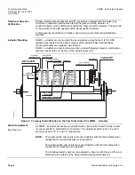
Page 8: ... gear end 10 0 30 50 0 0 10 0 30 50 50 10 10 0 30 70 0 10 0 30 50 CAM DRUM RELEASE BUTTON GEAR END EA0561R3 ACTUATOR POSITION SCALE SWITCH CAM I SET AT MAXIMUM SWITCH CAM II SET AT ZERO ECONOMY SWITCH CAM III SET AT MINIMUM ACTUATOR POSITION INDICATING POINTER CAM DRUM ASZ 1000 Ohm FEEDBACK POTENTIOMETER DIAL POINTER ACTUATOR POSITION INDICATING DIAL SINGLE SWITCH CAM POINTER DOUBLE SWITCH CAM POI...

Page 9: ...been set the cam drum must be manually aligned by pressing and holding the black cam drum release button see Figure 6 Rotate the cam drum until the 0 mark on the actuator position scale left scale on the cam drum is aligned with the gray actuator position indicating pointer The actual position of the SQM5 actuator is indicated by the gray actuator position indicating pointer see Figure 6 The posit...

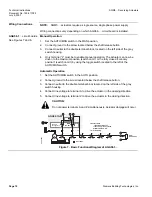
Page 10: ...ed economy position switch cam II by using the toggle switch located to the left of the AUTO MAN switch Automatic Operation 1 Set the AUTO MAN switch in the AUTO position 2 Connect ground to the screw located below the shaft release button 3 Connect neutral to the double terminal block located on the left side of the gray switch housing 4 Connect line voltage to terminal A to drive the actuator in...

Page 11: ...e power to the electronic circuit board 5 Connect line voltage to terminal LR to provide power when modulating Connect line voltage to Terminal LR only after removing power on terminals A and Z otherwise actuator damage may result 6 Connect line voltage to terminal A to drive the actuator to the maximum high fire purge position Once the maximum position is reached terminal 11 on switch I will be e...

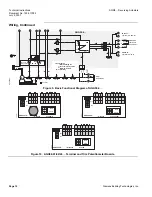
Page 12: ...tation brown black blue Economy Fully closed Minimum Low fire Maximum High fire Auxilliary IV VI III II I actuator switch AGA56 41 G board 4 20 mA AGA56 43 K board 0 10 V 135 Ohm AGA56 42 H board 0 135 Ohm Figure 9 Basic Functional Diagram of AGA56 4 Z A MAX MIN 0 MAN AUTO OPE MAX MIN LR N L Y Y EA0553R4 AGA56 41A 13 ZL G Board 4 to 20mA MAX MIN OPE MAX MIN Z A LR 13 N ZL L Y M U 0 EA0552R4 MAN AU...

Page 13: ...ltage to terminal L1 to provide power when modulating Connect line voltage to terminal L1 only after removing power on terminals A and Z otherwise actuator damage may result 6 Connect line voltage to terminal A to drive the actuator to the maximum high fire purge position Once the maximum position is reached terminal 11 on switch I will be energized to provide position feedback 7 Connect power to ...

Page 14: ...mA 1 2 3 11 21 M I II III IV V 12 22 13 23 14 15 24 25 4 5 1 2 13 3 21 12 51 N VI 16 26 6 wire leads A L Z ZL L1 N P ZF M U3 M U4 M Y0 M Y3 M Y1 M Y2 U2 U1 Economy Fully closed Minimum Low fire Maximum High fire Auxilliary IV VI III II I actuator switch common 0 2 V R B W MAN AUTO shown in auto position ASZ 1000 Ohm b a c for ccw rotation brown black blue Figure 11 Basic Functional Diagram of AGA5...

Page 15: ...trim potentiometer can now be gently adjusted to the required maximum position Return the OPE MAX MIN slide switch to OPE for operation Example of limit switch I and III and trim potentiometer settings Switch III setting Swit ch I setti ng 0 deg EA0562R1 MIN trim potentiometer setting M A X tr im p o te n ti o m e te r s e tt in g 90 deg Figure 13 Switch cam and Trim Potentiometer Setting NOTE The...

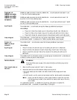
Page 16: ...le Input Signals The AGA56 9A circuit board accepts the following input signals Line voltage Power to A drives the actuator open to the setting of switch cam I Maximum Power to ZL drives the actuator closed to the setting of switch cam III Minimum Power to Z drives the actuator closed to the setting of switch cam II Economy 4 to 20 mA Signal to Y3 common to M 0 to 135 Ω Slide wire signal to Y0 pot...

Page 17: ...tion overriding all modulating input signals Use the potentiometer marked POS to adjust the override position to any setting within the setting range of switch cams I and III NOTE The input signal override can also be used for the ignition position of burners if different from the low fire position Parallel Operation Set Jumper J2 in position 1 upper position to configure the actuator for parallel...

Page 18: ...Features of SQM5x xxxxxAx Actuators Input Signals The AGA56 1A97 circuit boards accept the following additional input signal Line voltage Power to A drives the actuator open to the setting of switch cam I Maximum Power to Z drives the actuator closed to the setting of switch cam II Economy Power to switch III terminal 3 drives the actuator to the setting of switch cam III Minimum Output Signals Th...

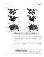
Page 19: ...t board and reverse The black wire remains connected to the middle terminal See Figures 17 and 17a 4 Remove the white plastic actuator position indicating dial by gently pulling while rotating in the clockwise direction See Figure 6 5 The actuator position indicating pointer located near the actuator gear end of the cam drum must point to the 0 mark on the actuator position scale scale on the cam ...

Page 20: ...cket installed on the inside base of the SQM5 actuator has four vertical slotted circuit board supports Remove the terminal section and circuit board s from the mounting bracket The actuator motor capacitor is attached to the lower section of the gray plastic switch housing using snap on holding clips Gently pull the capacitor forward until it unclips and temporarily place it on top of the gear ho...

Page 21: ...d downward until both supports snap into place Ensure that the four brown wires and the flat white connector cable which connect the two circuit boards are positioned correctly in their respective corners allowing the board to freely slide into place without pinching either wire See Figure 21 7 Connect the bundled blue black and brown potentiometer wires to the terminal block located on the ASZ po...

Page 22: ...of the switch housing f Connect the grounding wire marked 51 to the ground terminal located to the right of the auto manual switch EA0577R2 2 51 N 13 3 1 0 MAN AUTO I 11 21 1 2 22 12 II 3 23 13 III 4 24 14 IV 5 25 15 V 6 26 16 VI 7 27 17 VII 8 28 18 VIII TERMINAL BLOCK N Figure 22 AGA56 9A Circuit Board Installation 1 Remove the ASZ potentiometer if already installed on the SQM5 actuator See Poten...

Page 23: ...Figure 25 7 See Figure 26 and make the following connections to the actuator a Connect the wire marked 1 from the circuit board to switch I terminal 1 b Connect the wire marked 2 from the circuit board to switch II terminal 2 Connect the white wire marked 3 from the circuit board to switch III terminal 3 c Connect the wire marked 13 from the circuit board to switch III terminal 13 d Connect the ne...

Page 24: ... on the ASZ potentiometer circuit board EA0565R2 2 51 N 13 3 1 0 MAN AUTO N I 11 21 1 2 22 12 II 3 23 13 III 4 24 14 IV 5 25 15 V 6 26 16 VI 7 27 17 VII 8 28 18 VIII Figure 26 EA0566R1 L SHAPED CIRCUIT BOARD Figure 27 AGA56 1A97 Circuit Board Installation 1 Install the AGA56 1A97 circuit board into the two slotted circuit board supports located on the switch housing side of the actuator 2 Gently g...

Page 25: ...e button while manually rotating the cam drum 4 If installing a potentiometer without gear manually rotate the potentiometer pointer until the pointer is exactly in the min position See Figure 17 Firmly tighten the black potentiometer cam attachment screw while manually holding the potentiometer pointer in alignment Check the alignment again 5 If installing a gear model potentiometer manually rota...

Page 26: ...160 SQM5x xxxxxx3 models 0 to 90 SQM5x xxxxxx4 models 0 to 135 SQMSx xxxxxx6 models 0 to 160 Direction of rotation Reversible Shaft Selectable See Table 2 Custom versions on request Shaft disengagement Independent cam and drive shaft Number of auxiliary switches 4 switches standard maximum 6 Limit switches 2 switches standard Electrical rating of auxiliary switches 7 5 3 A 250 Vac Mounting positio...

Page 27: ...ncy 50 to 60 Hz Auto manual switch 2 position switch Manual toggle switch 3 position switch Ambient operating temperature 5 F to 140 F 20 C to 60 C Shipping temperature 58 F to 140 F 50 C to 60 C Weight 0 22 lb 0 1 kg AGA56 41A Electronic circuit boards Single potentiometer ASZ 1000 ohm is required Operating voltage 24 Vac 10 15 110 Vac 15 to 120 Vac 10 220 Vac 15 to 240 Vac 10 Operating frequency...

Page 28: ... to 20 mA 0 to 20 mA 0 to 10 Vdc 0 to 135 ohm Impedance Current input 300 Ω Voltage input 100K Ω Output signals 4 to 20 mA 0 to 20 mA 0 to 10 Vdc Max output load Current output 600 ohm Voltage output 1 5K ohm Zero adjustment MIN 0 to 75 Span adjustment MAX min 100 Split ranging SHIFT 4 to 20 mA on terminal ZF Input signal override POS Line voltage Vac on terminal P adjust with POS potentiometer Am...

Page 29: ...sion given is measured in inches Millimeters are shown in parentheses M 8 ALLOW 3 5 SPACE FOR COVER REMOVAL 1 3 16 30 5 8 16 2 5 8 67 1 4 6 1 3 16 30 1 7 16 36 EA0522R1 5 1 4 133 7 1 16 180 3 8 10 Pg 13 5 1 2 NPSM 1 4 20 UNC 7 1 16 180 5 16 8 5 6 7 16 164 5 16 7 5 1 16 1 1 8 3 5 EA0542R2 4 7 16 113 3 1 8 80 5 3 16 132 Figure 28 SQM5x xxxRxx Dimensions ...

Page 30: ...80 4 7 8 123 8 9 16 14 5 Figure 29 Mounting Bracket AGA57 3 L C 7 16 11 13 16 20 3 13 16 20 3 1 8 3 5 16 7 94 5 16 7 94 1 2 12 5 45 45 All non sized holes O 5 16 7 62 AGA57 4 3 1 8 80 4 7 16 113 5 5 16 135 2 3 8 60 4 4 3 4 120 65 5 16 7 94 5 16 8 73 5 16 8 73 7 5 16 185 2 1 4 57 15 1 9 16 40 6 7 16 164 2 3 8 60 64 1 1 2 38 1 1 5 8 42 2 50 8 1 11 16 43 EA0520R2 3 1 8 80 2 1 2 63 5 4 101 5 4 7 16 11...

Page 31: ... 60089 4513 U S A Your feedback is important to us If you have comments about this document please send them to SBT_technical editor us sbt siemens com Dimensions Continued AGA58 1 AGA58 2 AGA58 3 AGA58 4 AGA58 7 GEAR SIDE 0 12 3 0 39 10 0 35 9 M5 x 9 0 05 1 3 0 67 17 0 42 10 6 0 05 1 3 0 31 8 0 27 6 9 EA0543R1 7 09 180 1 25 5 0 79 20 0 35 9 1 25 5 0 43 11 0 27 6 9 0 42 10 6 0 20 5 0 85 21 5 0 78 ...

Reviews: