SQM5… Reversing Actuators
Technical Instructions
Document No. 155-517P25
July 9, 2007
Siemens Building Technologies, Inc.
Page 9
Switch Adjustment,
Continued
NOTE:
If a potentiometer is installed, the adjustable range of the switches depends
on the range of the potentiometer.
SQM5x.xxxxx
A
x actuators may be adjusted between 0
°
and 160
°
.
SQM5x.xxxxxx
3
actuators have a 90
°
potentiometer and the switches must be
adjusted only between 0 and 90
°
.
SQM5x.xxxxxx
4
actuators have a 135
°
potentiometer and the switches must
be adjusted only between 0 and 135
°
.
Shaft Adjustment
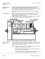
See Figure 6.
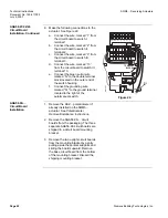
The actuator shaft can be disengaged by pressing the silver shaft release button. The
button is located above the grounding screw, under the hinged terminal protection
cover, and to the right of the auto/manual switch. After pressing the shaft release button
in and slightly upward, the shaft can be manually rotated. After the shaft has been
manually aligned to the closed position, re-engage the shaft by pushing the shaft
release button downwards.
Cam Drum Adjustment
See Figure 6.
Position Indicating Dial
Adjustment
Once the shaft has been set, the cam drum must be manually aligned by pressing and
holding the black cam drum release button (see Figure 6). Rotate the cam drum until
the “0” mark on the actuator position scale (left scale on the cam drum) is aligned with
the gray actuator position indicating pointer.
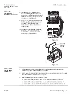
The actual position of the SQM5… actuator is indicated by the gray actuator position
indicating pointer (see Figure 6). The position is also displayed by the indicating dial
through the housing’s window. Ensure that the actuator position indicating dial is
aligned with the actuator position scale. If necessary, rotate the dial in the clockwise
direction.
CAUTION:
Turning the dial in the counterclockwise direction may loosen the
potentiometer locking screw.
Wiring
Electrical Connection
SQM5… actuators are equipped with two removable conduit connection plates located
on the upper corner of the gear housing. Each plate is provided with two threaded
connections for 1/2" NPSM conduit connectors. The use of flexible stranded wire is
recommended.
Grounding
CAUTION:
To avoid electro-magnetic interference, the SQM5… actuators must be
grounded.
The ground terminal is located to the right of the auto/manual switch.
Disconnect the circuit board wire marked 51 during high voltage testing.
Reconnect it to the grounding terminal after the test.

