background image

CM1N4573E / 06.2001

Siemens Building Technologies

6/8

Landis & Staefa Division

Operation

To IEC 721-3-3

Environmental conditions

Class 3K5

Temperature

5 ...

+

50 °C

Humidity

5... 95 %rh

Transport

To IEC 721-2-3

Environmental conditions

Class 2K3

Temperature

25 ...

+

70 °C

Humidity

< 95 %rh

Storage

To IEC 721-1-3

Environmental conditions

Class 1K3

Temperature

5 ...

+

50 °C

Humidity

5 ... 95 %rh

Meets the requirements for CE marking:

EMC Directive

89/336/EEC

Low Voltage Directive

73/23/EEC

Dimensions

See “Dimensions”

Weight

SQS35.00, SQS35.03, SQS65, SQS65.2,
SQS85.00, SQS85.03
Excluding packaging

0.5 kg

With packaging

0.6 kg

SQS35.50, SQS35.53, SQS65.5
Excluding packaging

0.6 kg

With packaging

0.7 kg

Actuator housing

Plastics

Housing cover and manual adjuster

Plastics

Gear train and stem with coupling

Plastics

ASC9.6 auxiliary switch for SQS35… and SQS85…
Switching capacity

AC 250 V, 10 A resistive / 3 A inductive

M

45

73

G

0

1

Y1

3

Y2

100%

0%

11

12

N

L

4 5

Cm1

Cm2

c1

21

Y1

Y2

H4

N

M

100%

0%

max. 50%
0%

M

n

Cm1

Cm2

c2

45

73

G

0

2

SQS35.00, SQS35.03
AC 230 V, 3-position, non-spring return

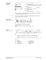
Cm1Limit switch 100 % stroke
Cm2

Limit switch 0 % stroke

c1

ASC9.6 auxiliary switch can be fitted

L

Volt-free loop terminal for live wire

SQS35.50, SQS35.53
AC 230 V, 3-position, with spring return

c2

Built-in auxiliary switch with fixed preset
minimum flow limit control.
(Factory-fitted, not accessory like ASC9.6)

M

90

19

0

Y1

3

Y2

100%

0%

11

12

G

L

4 5

Cm1

Cm2

c1

SQS85.00, SQS85.03
AC 24 V, 3-position, non-spring return

Cm1Limit switch 100 % stroke
Cm2Limit switch 0 % stroke
c1

ASC9.6 auxiliary switch can be fitted

L

Volt-free loop terminal for live wire

Industry standards

Dimensions / Weight

Materials

Accessories

Connection
diagram

SQS35...

SQS85...

Summary of Contents for SQS35.53

Page 1: ...ion and with manual adjustment Spring return actuators with position indication and without manual adjustment Used to operate 2 port and 3 port valves with a 5 5 mm stroke For valve types VVG44 VVG55 VVP45 VMP43 VMP44 VMP45 VXG44 VXP45 VVI52 Area of application in accordance with IEC 721 3 3 Class 3K5 Ambient temperatures 5 50 C Temperature of medium in the connected valve 2 130 C The use of mount...

Page 2: ... 0 1mA 24V C B Relationship between the DC 0 10 V or DC 2 10 V control signal and the volumetric flow rate Control signals Y DC 0 10 V or DC 2 10V R 0 1000 Ω Flow characteristic log Equal percentage valve characteristic factory setting lin Linear valve characteristic Flow range k V100 Volumetric flow 100 k V0 Volumetric flow 0 Volumetric flow rate l i n lo g 4573D01 k V100 k V0 0 V 2 V 10 V 10 V C...

Page 3: ...ng return function to DIN 32730 Load dependent switch off in stroke limit positions Selectable flow characteristic equal percentage or linear for SQS65 actuators in conjunction with valve types VVG44 VVI52 and VXG44 Directly impacting manual adjustment for all non spring return actuators SQS35 00 SQS35 03 SQS65 SQS65 2 SQS85 Position indicator on all SQS35 SQS65 SQS85 actuators Accommodation for a...

Page 4: ...characteristic must be set to lin for valve types VVG55 VMP VVP and VXP The admissible temperatures see Application and Technical data must be observed If an auxiliary switch is required its switching point must be indicated on the plant schematic Permissible Not permissible Instructions for fitting the actuator to the valve are shown on the back of the actuator housing The instructions for access...

Page 5: ...tly fitted to the valve before re commissioning Operating voltage SQS35 AC 230 V 15 50 60 Hz SQS65 AC 24 V 20 50 60 Hz SQS85 AC 24 V 20 50 60 Hz Power consumption SQS35 00 2 5 VA SQS35 03 3 5 VA SQS35 50 5 VA SQS35 53 6 VA SQS65 SQS65 2 4 5 VA SQS65 5 7 VA SQS85 00 2 VA SQS85 03 2 VA Switching capacity of limit switchesTerminals 11 or 12 SQS35 SQS85 AC 250 V 6 A resistive 2 5 A inductive Type of c...

Page 6: ...Gear train and stem with coupling Plastics ASC9 6 auxiliary switch for SQS35 and SQS85 Switching capacity AC 250 V 10 A resistive 3 A inductive M 4573G01 Y1 3 Y2 100 0 11 12 N L 4 5 Cm1 Cm2 c1 21 Y1 Y2 H4 N M 100 0 max 50 0 M n Cm1 Cm2 c2 4573G02 SQS35 00 SQS35 03 AC 230 V 3 position non spring return Cm1Limit switch 100 stroke Cm2 Limit switch 0 stroke c1 ASC9 6 auxiliary switch can be fitted L V...

Page 7: ...n the connection diagrams How many and which of these are used depends on the system If a device is connected to terminal R the factory fitted bridge across R M on the printed circuit board must be cut through SP SN Y 1 2 3 R M M R G0 Y G Y Y R M U GO AC 24 V N1 R1 F1 K1 P1 Y1 4573A01 G SP SN LS NS Y 1 3 R M G Y G0 R M M R U G0 Y G 4573A02 AC 24 V N1 R1 F1 P1 K1 Y1 Equipment F1 Frost detector K1 O...

Page 8: ...mensions in mm 60 68 128 28 88 120 134 G 80 32 111 ø 18 5 Pg 11 4573M01 Height of actuator after fitting on valve 100 mm Minimum clearance from wall or ceiling 200 mm for mounting connection operation service etc Dimensions ã 2000 Siemens Building Technologies Ltd Subject to changes ...

Reviews: