background image


Installation Instructions 

Document No. 129-253  

May 8, 2019 

SSC Series Electronic Valve Actuator 


Item Number 129-253-07, Rev. FA 


Page 1 of 

5


Product Description 

The SSC series actuator requires a 24 Vac, Class 2 
supply and provides a 0 to 10 Vdc or Floating (three-
position) control signal. The actuator controls a 
Powermite

™ 599 Series MT Series valve with a 

7/32-inch (5.5-mm) stroke.  

Warning /Caution Notations 

WARNING: 


Personal injury or loss of life 
may occur if you do not 
perform a procedure as 
specified.


CAUTION: 


Equipment damage or loss of 
data may occur if you do not 
follow a procedure as 
specified.


Product Numbers 

SSC61U 

0 to 10 Vdc, proportional control, 


non-spring return (fail-in-place) 

SSC61.5U 

0 to 10 Vdc, proportional control, 


spring return (fail-safe) 

SSC81U  

Floating control, non-spring return  


(fail-in-place) 

SSC81.5U  

Floating control, spring return  


(fail-safe) 

Contents 

One SSC actuator  

Estimated Installation Time 

20 minutes  

Required Tools 


Small Phillips head screwdriver 


Small flat-blade screwdriver 


Wire stripper 


Prerequisites 


WARNING: 

1.  If mounting the actuator to a valve already 

in line, either close the shut-off in the 
piping (upstream first, then downstream) or 
switch off the pump to allow the differential 
pressure in the valve to drop.  

2.  Disconnect the controller power before 

replacing the actuator.  

3.  If high voltage cable is co-located with the 

SSC actuator, conduit or shielded wire may 
need to be used.  


CAUTION:


Before applying power, make certain a valve is 
connected to the actuator.  
 
If applying power to the actuator when a valve is 
not connected, the actuator will respond to a 
control signal and the shaft will extend until it 
reaches its maximum end stop. Thereafter, it will 
not respond to any signal.  
 
If this occurs, disconnect the power. Turn the 
manual position indicator on the top of the 
actuator to the 

0

 position and verify the actuator 

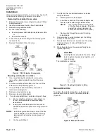
shaft retracts completely. See Figure 4. 
 
Connect a valve to the actuator and reapply the 
power. The actuator will return to normal 
operation. 

Mounting 

The vertical position is recommended for mounting 
the actuator. See Figure 1.  


Figure 1. 

Acceptable Actuator Mounting Positions.  


CAUTION:


Mount actuator at a 45° angle from vertical when 
using on low pressure steam systems to reduce 
radiant heat that can damage the actuator. 

Summary of Contents for SSC Series

Page 1: ...NG 1 If mounting the actuator to a valve already in line either close the shut off in the piping upstream first then downstream or switch off the pump to allow the differential pressure in the valve to drop 2 Disconnect the controller power before replacing the actuator 3 If high voltage cable is co located with the SSC actuator conduit or shielded wire may need to be used CAUTION Before applying ...

Page 2: ...ficient cable to complete wiring terminations b Insert plenum cable adapter into flex conduit adapter and secure in place with wiring retention screw NOTE Insert wiring retention screw in hole of the flex conduit adapter The hole nearest the wiring terminals is to secure the terminal cover in place c Continue with Step 8 7 For 3 8 inch flex conduit applications complete wiring as follows a Discard...

Page 3: ...supply transformer rating by summing the total VA of all actuators used The maximum rating for a Class 2 step down transformer is 100 VA Do not power more than 10 actuators with one transformer Use 0 5 amp on secondary actuators Y2 Retracts actuator shaft Y1 Extends actuator shaft G System potential Figure 6 SSC81U NSR Floating Control Figure 7 For Non Triac Driven Controllers Figure 8 For Triac D...

Page 4: ...Output Shaft 0 Retracted 1 Extended NOTE 0 and 1 markings are intended for reference only and not stroke measurement Figure 11 Position Indicator Shown in 0 Position Troubleshooting Check the wiring for the proper connections References Technical Instructions Document No EA 599 15 Powermite 599 Series SSC Electronic Valve Actuator 24 Vac Proportional Control 155 313P25 EA 599 16 Powermite 599 Seri...

Page 5: ...marks of their respective owners 2019 Siemens Industry Inc Siemens Industry Inc Smart Infrastructure 1000 Deerfield Parkway Buffalo Grove IL 60089 4513 USA 1 847 215 1000 Your feedback is important to us If you have comments about this document please send them to Sbt_technical editor us sbt siemens com Document No 129 253 Printed in the USA Page 5 of 5 Dimensions Figure 12 SSC Actuator Dimensions...

Reviews: