ST750
G
ENERAL
H
ANDBOOK
667/HB/33750/000
Page 53
Issue 6
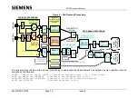
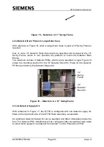
Figure 15
– Detectors in 11” Swing Frame
4.8.2 Detector Back Planes in Large Outer Case
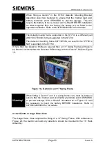
With reference to Figure 16, when
a Large Outer Case is used a 19” Swing Frame is
required.
One or more 19
” Detector Rack Kits should be specified and mounted to the 19”
Swing Frame, which in turn provides the platform to mount the Detector Back
Planes.
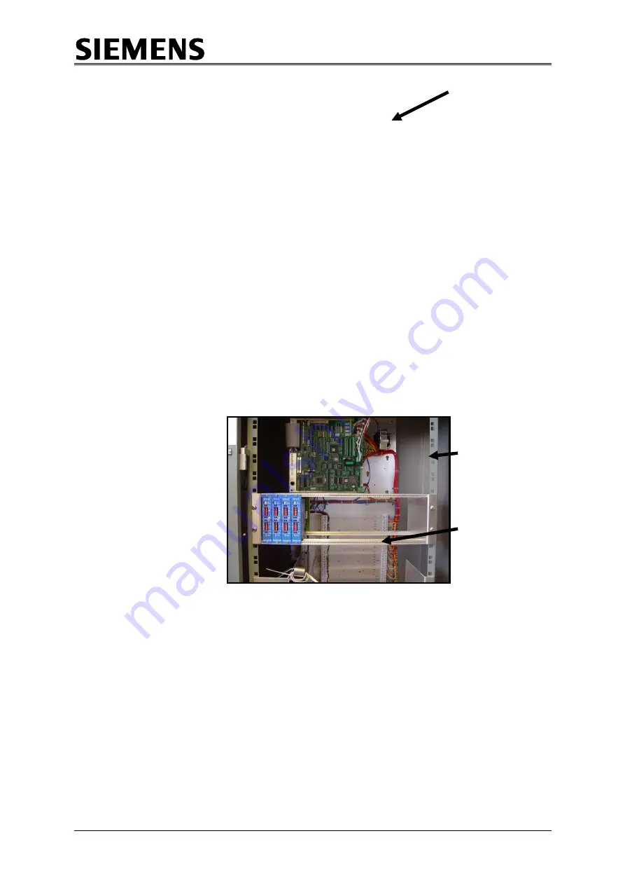
The maximum number of Detector PCBs, which can be specified, is eight. Figure 16
shows the mounting position for the 19” Detector Rack Kit. Power for the Detector
PCBs is provided by the Detector Supply Kit.
Figure 16
– Detectors in a 19” Swing Frame
4.9 2A Detector Supply Kit
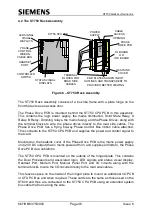
With reference to Figure 17, the ST750 is configured with one detector supply kit,
fitted on the right hand side of the ST750 Rack Assembly, as standard.
An additional Detector Supply kit can be specified and fitted immediately below the
first. The Detector PSU transformer will be configured with conventional main leads
to allow mains supply to be obtained from socket 1 on the Phase Driver PCB.
19”
Detector
Rack Kit
19”
Swing
Frame

