ST750
G
ENERAL
H
ANDBOOK
667/HB/33750/000
Page 67
Issue 6
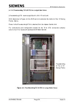
Figure 25 - Stool Installation, Large Cabinet
5.6 Cabling to the ST750 small and large cabinets
All cables into the ST750 controller cabinets should be fed through the ducts and
into the stool/base as close to the controller termination positions as possible. This
is to prevent unnecessary damage being caused should any cables need to be
moved once they are in place. Care must be taken not to obstruct the Electricity
Supply Company cut-out with any cabling.
The outer sheathing must be stripped to expose the armouring. It is suggested that
between 55mm and 65mm of the inner sheathing is left above the Hose Clip and
stripped armour (see Figure 1), which is more than normally required for other
Cabinet Assemblies. This is due to the height of the CET bar and its staggered
fixing nature. The additional height ensures that double insulation is provided where
the cable rests against the metal items. Sufficient further conductor length must also
be allowed to reach the terminal blocks via the proper routing.
The cable is inserted in the CET ring and the armoured wires are bent outwards and
down against the ring. A hose clip is then placed over the armoured wires and
tightened up. The armouring must be stripped, leaving a small amount (approx. 0 to
2mm) below the level of the CET ring.
Apply silicone sealant
between stool and case
996/4/22026/100

