ST750
G
ENERAL
H
ANDBOOK
667/HB/33750/000
Page 80
Issue 6
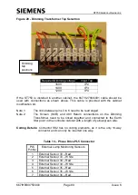
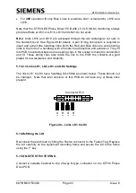
Figure 29 - Dimming Transformer Tap Selection
S
C
R
0
Required Dimming voltage
Input Tap
160V
IP2
140V
IP3
120V
IP4
If the ST750 is installed in another cabinet, the 667/1/27868/001 cable should be
used with connections as shown above. This cable is provided with the cabinet
modification kit.
Note 1:
The links between pins 3 to 6 need to be rearranged.
Note 2:
The Screen (SCR) and 48V Return connections on the Dimming
Transformer need to be linked together and connected to the Earth
Star point in the controller cabinet with a length of yellow/green wire.
Coding Details:
Connector SK2 has no coding elements, as it is the only 10-way
connector and can only be inserted one way.
Table 13
– Phase Drive PL5 Connector
PL5
Pin No
External Lamp Monitoring Sensors
1
External Sensor 33
– Red
2
External Sensor 33
– White
3
External Sensor 34
– Red
4
External Sensor 34
– White
5
External Sensor 35
– Red
6
External Sensor 35
– White
7
External Sensor 36
– Red
Dimming
tap
positions

