ST750
G
ENERAL
H
ANDBOOK
667/HB/33750/000
Page 82
Issue 6
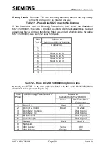
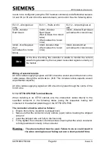
needs to be configured (using the ELV handset command) and affects what sensors
34 and 38 (or 36 and 40 on the second stream) can monitor. See the following table:
ELV:0
– All signals at
230v
ELV:1
– Waits at 48v
ELV:2
– All ped signals at
48V
34/36
– Monitor
Red+Green
34/36
– Monitor
Red+Green
(Red & Green thro’ toroid
twice)
(Wait cables thro’ toroid
once)
34/36
– Monitor Red+Green
(all cables thro’ toroid once)
38/40
– Not Required
Wait
(all cables thro’ toroid
twice)
38/40
–Monitor Wait
(Wait cables thro’ toroid
once)
38/40
–Monitor Wait
(all cables thro’ toroid once)
Note
At the time of writing, the controller is unable to monitor the current
waveform generated by the low power near-sided signals currently on
the market.
Wiring of external toroids
All drive cables supplying signals at 230V should be wound around the toroid so the
cable passes through the centre twice. (N.B. This includes vehicle aspects as well
as pedestrian aspects.)
All drive cables supplying signals at 48V should only pass through the centre of the
toroid once.
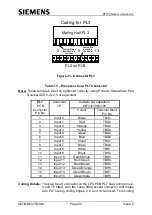
5.11.2 ST750 CPU PCB Terminal Blocks
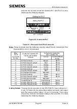
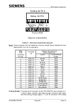
When installing in an ST750 cabinet, wire the intersection cables directly to the
specified connector in the following tables (using the respective mating half
contained in the attached plastic bag) on the ST750 CPU PCB.
The connectors must be wired as follows:
•
Ensure 9mm of wire insulation is stripped back
•
Make sure that the connector is fully undone (open) before inserting the stripped
wire end
•
Insert the stripped wire end fully to the back stop
•
Firmly tighten the connector’s terminal screw ensuring that the wire’s conductor
is firmly positioned correctly in the connector
Warning:
The above method must be used. Failure to do so could result in
the wires coming loose or falling out over a short period of time.

