ST750
G
ENERAL
H
ANDBOOK
667/HB/33750/000
Page 91
Issue 6
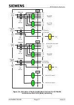
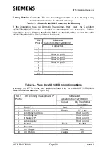
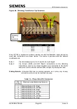
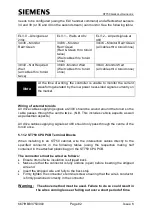
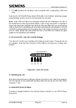
5.13.2 Phase Drive PCB Switches, Links and Fuses Setup
T
AG
4
T
AG
3
T
A
G
2
T
AG
1
L
K
2
1
L
K
2
2
P
L8
1
6
PL
7
PL
6
1
16
PL
3
PL5
LK15
LK16
LK17
LK18
LK19
LK20
SK
2
PL1
24v Power Supply Unit
L
K
3
L
K
4
L
K
1
L
K
2
F6 and F8 are
Pedestrian Wait/
Vehicle Ambers
F10 and F11 are
Pedestrian Red/
Green
R
ib
b
o
n
c
a
b
le
c
o
n
n
e
c
te
d
to
6
4
-w
a
y
c
o
n
n
e
c
to
r
o
n
C
o
n
tr
o
ll
e
r
B
o
a
rd
F1
F4
F11
F10
F3
F2
F9
F8
F7
F6
External Analogue I/Ps
Connector (Current Coil)
P
h
a
s
e
1
&
2
D
ri
v
e
O
/P
s
C
o
n
n
e
c
to
r
P
ha
s
e
5
&
6
D
ri
v
e
O
/P
s
C
o
nn
e
c
to
r
S
T
7
0
0
P
S
U
C
o
n
n
e
c
to
r
M
A
P
1
4
0
P
S
U
C
o
n
n
e
c
to
r
Mains I/P
Connector
External Mains and
48V Connections
SK1
1
16
PL
2
Mains I/P
24V O/P
Dimming
Transformer
Connector
FUSE
= 48v
P
h
a
s
e
3
&
4
D
ri
v
e
O
/P
s
C
o
n
n
e
c
to
r
Figure 39
– ST750 Phase Drive PCB Assembly

