ST750
G
ENERAL
H
ANDBOOK
667/HB/33750/000
Page 95
Issue 6
With all signals covered (bagged), use the LMP handset command, which causes
each colour on each phase to illuminate in turn, whilst other persons are checking
the aspects. Care must be taken to ensure that any traffic on the junction does not
mis-read the signals and cause an accident. In addition, a visual check of the wiring
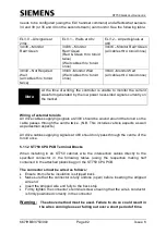
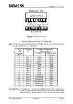
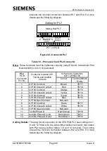
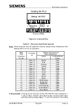
must be carried out, to ensure that the individual approaches are wired correctly as
shown in Figure 27.
The ST750 signals can now be switched on (using the switch on the manual panel)
and the ST750 powered up normally.
If the solar cell and signal dimming are not required then the following test can be
ignored.
1. Cover the photoelectric cell for at least one minute to exclude any light and
check that the signals are dimmed.
2. Remove the cover from the photoelectric cell and after at least one minute
the signals should revert to the bright condition.
If detectors are installed then they should be set up as defined in the Detector
Information Handbook.
Set up the date and time.
Check that the Lamp Monitor has correctly learnt all the lamp loads, using the KML
and KEL handset commands, described in the Controller Handset Handbook.
Check that there are no unexplained errors in the fault log.
This completes the testing and the site should be ready for Customer acceptance.
5.16 ST750 START-UP SEQUENCE
When the ST750 is initially powered up, it performs various internal checks before
starting normal operation. While these checks are being performed the green
heartbeat LED flickers and the red system error LED remains on.
If these tests fail then there is a serious fault on the CPU PCB and the PCB should
be replaced. The error message is repeatedly written to the handset display at 1200
baud, and no other handset operations can take place. Refer to the ST900/750
Handset Handbook for full detail of error messages (section 1.3.2)
In addition to the above internal checks, the ST750 goes on to check the contents of
its battery backed RAM, e.g. the fault log and checksum on the timings data, before
attempting to switch on the signals.
Once the ST750 is running normally, it extinguishes the red system error LED and
the green heartbeat LED flashes.


