background image


ST750


G

ENERAL 

H

ANDBOOK


667/HB/33750/000 

Page 99 

Issue 6 


Warning! 

The following tests will result in the signals extinguishing


  Test  the  300mA  RCD  (if  fitted)  by  pressing  the  test  button.  The  breaker  should 

operate immediately. If the contract specifies the testing of RCD speed, then this 
test  should  be  performed  using  the  appropriate  equipment.    If  the  RCD  is  faulty 
then the results should be recorded the unit replaced.  Any replacement unit is to 
be similarly tested to ensure correct operation before leaving site. 


  Check  the  termination  panel(s)  and  master  switch  panel  within  the  Cabinet  and 

ensure  that  there  are  no  loose  fixings,  or  damage  to  these  panels.  Tighten  any 
loose fixings and carry out any repairs that are necessary. 


  Check  the  logic  assembly  and  other  assemblies  within  the  ST750  are  securely 

fixed. Retighten loose fixings as necessary. 


  Check that all fuses are secure in their holders.. 


Warning! 

It  is  strongly  recommended  that  the  ST750  supply  is  isolated 
before any fuses are checked 


  Check  wiring  and  cableforms,  particularly  ribbon  cables  for  damage.  Replace or 

re-route as appropriate. 


  The  battery  on  the  ST750  CPU  PCB  must  be  replaced  if  it  has  failed.  Any 

replacement  battery  should  be  suitably  marked  with  an  appropriate  date  label. 
Having done this, the ST750 records should be updated accordingly. 

 
The following tests require the ST750 to be powered and running normally. 
 

  Tests of the Voltage Drop of Neutral Conductors. This test should be carried out 

during each periodic/annual inspection as a simple check of neutral cables, which 
can also provide a good indication of the state of the intersection cabling. 


(i)  Take a digital multi-meter or voltmeter and set it to measure 240 volts AC 

(RMS). 

 
(ii)  Select  a  phase  and  wait  until  its  green  has  just  terminated.  Measure  the 

voltage  between  the  Cabinet  Assembly  neutral  and  the  green  feed;  the 
voltage  should  be  no  greater  than  4  volts  (RMS)  throughout  the  signal 
cycle,  except  when  the  phase  next  goes  to  green.  If  the  voltage  between 
the green feed and neutral is greater than 4 volts then do the following: 
 
(1) Check  all  joints  in  the  appropriate  neutral  cable  run,  ensure  that  they 

are all tight and none are seriously corroded, replace or tighten them as 
necessary. 


Summary of Contents for ST750

Page 1: ...ND APPROVED Siemens Mobility Limited 2018 All rights reserved The information contained herein is the property of Siemens Mobility Limited and is supplied without liability for errors or omissions No part may be reproduced or used except as authorised by contract or other written permission The copyright and the foregoing restriction on reproduction and use extend to all media in which the informa...

Page 2: ...B 33750 000 Page 2 Issue 6 Change History Issue Change Ref Date 1 First Issue 11 February 2009 2 TS004961 27 February 2009 3 TS005209 28 August 2009 4 TS005637 31 August 2010 5 TS005954 10 February 2011 6 TS009064 06 December 2018 ...

Page 3: ...ed to the following a The equipment must be correctly connected to the specified incoming power supply b The equipment must be disconnected isolated from the incoming power supply before removing any protective covers or working on any part from which the protective covers have been removed c This equipment contains a Lithium battery that must be disposed of in a safe manner If in doubt as to the ...

Page 4: ...on the rear of the Cabinet should be opened since the Controller Switch on the front of the ST750 does not isolate both sides of the supply When re commissioning signals the following sequence is recommended 1 Switch OFF the Cabinet Assembly at the master switch 2 Switch ON the lamps on off switch on the manual panel 3 Switch ON the Cabinet Assembly at the master switch More specific safety inform...

Page 5: ... not guarantee isolation of the equipment WARNING These this controller s require specific configuration to enable them it to function correctly when installed The configuration process is a complex activity should only be carried out by persons who are adequately trained have a full understanding of the needs of the county or region where the controller is to be used and are experienced in the ta...

Page 6: ... of the ST750 Rack Assembly Cabinet Assembly or signal poles Safety Warning Lithium Battery This equipment contains a Lithium battery Do not short circuit recharge puncture take apart incinerate crush immerse force discharge or expose to temperatures above the declared operating temperature range of the product otherwise there is a risk of fire or explosion Batteries should be handled and stored c...

Page 7: ...0 2 3 MAINS SUPPLY 21 2 3 1 ELECTRICAL NOISE 22 2 4 DETERMINATION OF LOADING AND POWER CONSUMPTION 22 2 4 1 ST750 SUPPLY REQUIREMENTS 23 2 4 2 LAMP DRIVE CAPABILITY 23 2 4 3 CALCULATION OF AVERAGE SIGNAL LAMP POWER 25 2 4 4 INTERSECTION S POWER REQUIREMENTS FOR RUNNING COSTS ESTIMATE 25 2 4 5 CONNECTION TO UN METERED SUPPLIES UMS 26 2 4 6 DETECTOR POWER SUPPLIES 27 2 4 7 AUDIBLE AND TACTILE SUPPLI...

Page 8: ...A 60 5 INSTALLATION AND COMMISSIONING 61 5 1 PRE INSTALLATION CHECKS 61 5 1 1 HARDWARE CHECK 61 5 1 2 DIMMING TRANSFORMER TAP SETTING 61 5 2 ST750 CABINET PREPARATION 62 5 3 SITE SUITABILITY 62 5 4 INSTALLATION OF THE ST750 SMALL CABINET 63 5 4 1 INSTALL CONTROLLER CABINET AND STOOL 64 5 5 INSTALLATION OF THE ST750 LARGE CABINET 65 5 5 1 REMOVE THE CONTROLLER CABINET FROM THE STOOL 66 5 5 2 INSTAL...

Page 9: ...in Small Outer Case with Detector Swing Frame 43 Figure 4 ST750 in Small Outer Case configured with optional 11 Swing Frame 44 Figure 5 ST750 in Large Outer Case configured with optional 19 Swing Frame 45 Figure 6 ST750 Rack Assembly 46 Figure 7 CPU and Phase Driver Cards 47 Figure 8 I O Expansion Card 47 Figure 9 CPU LEDs 48 Figure 10 Master Switch Assembly 49 Figure 11 Mains Dimming Transformer ...

Page 10: ...set 107 Figure 42 Fuse Ratings 115 Tables Table 1 ST750 Supply Requirements 23 Table 2 ST750 Lamp Drive Capability 23 Table 3 ST750 Lamp Load Watts 24 Table 4 Detector Power Consumption 24 Table 5 ST750 Cabinet Assembly Size and Weight 31 Table 6 Phase Drive PL6 Connector 72 Table 7 Phase Drive PL7 Connector 73 Table 8 Phase Drive PL8 Connector for ST750 Phase Driver PCB 6 Phase 74 Table 9 Phase D...

Page 11: ...ection Design Publisher Reference Number Document Title 1 Siemens 667 DS 20664 000 Traffic Signal Junction Cable Design Certification 2 Siemens 667 HE 31699 000 Loop Inductance and Turns Calculation Spreadsheet 3 Siemens 667 DZ 33750 000 ST750 Family Tree 1 3 2 Essential Documents Controller Publisher Reference Number Document Title 4 Siemens 667 SU 32900 000 ST900 750 Family Firmware and Hardware...

Page 12: ...67 CC 29000 002 24 Volt Power Distribution Small Cabinet 22 Siemens 667 CC 29000 003 24Volt Power Distribution Large Cabinet 1 4 Pre Requisites Anyone undertaking installation commissioning and first line maintenance on the ST750 controller will also need the ST900 750 Family Handset Handbook 667 HH 32900 000 This provides details of how to access the controller handset port through which the user...

Page 13: ... 4 13651 000 1 5 Definitions Cabinet Assembly The ST750 Rack Assembly installed in the ST750 Cabinet with associated equipment mounting frame mounting stool mains distribution power supplies electronic control and phase switching Configuration data also referred to as customer s data and site specification Data supplied by customer as to how the ST750 is to function EM Controller identification nu...

Page 14: ...F Cableless Linking Facility CLS Central Light Source CPU Central Processing Unit DC Direct Current DFM Detector Fault Monitor ELV Extra Low Voltage EPROM Erasable Programmable Read Only Memory FT Fixed Time IC Integrated Circuit IC4 ST800 Configurator I O Input Output I P Input LED Light Emitting Diode LV Low Voltage ms milliseconds NLM No LMF Module OMU Outstation Monitor Unit OTU Outstation Tra...

Page 15: ...ST750 GENERAL HANDBOOK 667 HB 33750 000 Page 15 Issue 6 UTMC Urban Traffic Management and Control VA Vehicle Actuated ...

Page 16: ...ly Manual Panel Master Switch Assembly and a Dimming Transformer It may also be fitted as a Cuckoo into many existing cabinets when supplied as a Rack Assembly consisting of the power phase assembly and a CPU There are a number of conversion kits available that enable it to be installed into other cabinets The ST750 s electronics consist of three PCBs The CPU PCB that contains most of the logic wh...

Page 17: ...current outputs and can monitor Helios LV CLS NLM signals See 667 HB 32921 007 in Section 1 3 2 for further details The controller conforms to the UK Highways Agency specification TR2500A 2 1 1 Single Pedestrian Controller The ST750 Single Pedestrian Controller consists of one vehicle phase and one pedestrian phase with a minimal set of I O to perform all the functions of 2 phase Pelican Puffin or...

Page 18: ...pedestrian crossings detailed in TR2500A Type of Crossing Ped Signal Position Pedestrian to Vehicle Clearance Period Pelican Far side Vehicle Flashing Amber Pedestrian Flashing Green Puffin Near side Vehicle Red Pedestrian Red Pedestrian Far side Vehicle Red Pedestrian Blackout Toucan Far side Vehicle Red Pedestrian Blackout Toucan Near side Vehicle Red Pedestrian Red These are described in more d...

Page 19: ...inserted which is cancelled when all the kerbside detectors for the phase go inactive DFM DFM Faults on the individual I O lines no longer appear in the Fault Log Data FLD and should be interrogated using the DSF handset command which also displays the I O Line Number and IC4 Name as well as indicating whether the input failed active 1 or inactive 0 DFM The Reset DFM facility RDF 1 for example wil...

Page 20: ...to replace an existing or faulty ST700 CPU board but it is NOT possible to use an ST700 CPU board to replace an existing or faulty ST750 CPU board To use an ST750 CPU in an ST700 it is required to change the firmware PROM to PB800 In this case the relevant ST700 configuration will also need to be downloaded prior to use Warning On NO ACCOUNT is it permitted to downgrade an ST750 site to an ST700 s...

Page 21: ...ENT OF THE SUPPLY MUST NOT EXCEED 16 000 AMPS Frequency 50Hz 2Hz or 60Hz 2Hz Mains Brownout Continues operating with up to 50ms loss of mains Mains Fail Restarts without operator intervention Battery Support Primary cell Lithium battery provides support for the following during power failures a Clock Synchronisation programmable up to 31 days b Timing Data greater than one year A large capacitor p...

Page 22: ...o ensure the inductive switching does not cause interference The ST750 design is also extremely tolerant of externally generated electrical interference Care is taken to avoid earth loops using a Star point earthing system to which the cabinet the internal metalwork the junction cabling and the mains earth is connected The arrangement and partitioning of the equipment is carefully organised to red...

Page 23: ...Capability Max Current Amps Max Power Watts Maximum lamp current that the ST750 can supply including short term illumination i e red amber 8A 1840W Maximum lamp load for each triac output on the phase drive PCB 4A 230V or 4A 48V 920W or 192W Table 2 ST750 Lamp Drive Capability Output Type Lamp Load Bright Maximum Quantity per triac output Lamp Monitoring 230V Halogen 63W 14 Yes Max 8 per sensor 23...

Page 24: ...Watts Siemens ST4R ST4S detectors 2 4 watts per detector Sarasota MTS36Z 2 channel or MTS38Z 4 channel detectors NB The power consumption is the same for both 2 and 4 channel units 3 watts per detector Microsense detectors 6 watts per detector Table 4 Detector Power Consumption A A B B C C C A D D A C 2 Detector Cards used but not shown Pedestrian Wait Indicator Box on pole Pedestrian Red Green Si...

Page 25: ...V 240V mains supply 1 Calculate the total average controller power 2 Calculate the total average lamp power for the junction as shown in 2 4 3 3 Add the total average signal lamp power to the total average controller power Total average controller power is calculated as follows Average Controller power Average Detector Power See section 2 4 1 A controller is rated at 40 watts single or dual Pedest...

Page 26: ...e plus Total average Controller Power Therefore for the theoretical crossing in Figure 1 Total average Junction Power Dimmed 916W x 160V 240V 46W 657 W 2 4 5 Connection to Un Metered Supplies UMS If the ST750 is to be connected to an unmetered supply UMS equipment codes for the agreed power consumption of the controller and all associated equipment may be found on the Elexon web site General infor...

Page 27: ...The Audible and Tactile power supplies on the ST750 are designed to provide a DC voltage between 10V and 24V and typically provide a maximum of 100mA at 18V DC The ST750 provides three audible outputs on each of the 2 pedestrian phases These are located on the CPU card PL2 Phase D and PL3 Phase B Pin 11 is titled Tactile Phase n This is intended to interlock a tactile unit via the tactile PSU inte...

Page 28: ... Tactile output is used to control the tactile PSU interlock signal input 2 5 PHASES The ST750 Pedestrian Controller supports either 2 Real Phases for a single pedestrian crossing or 4 Real Phases for a dual pedestrian crossing The ST750 Small Non UK Controller can support up to 6 Real Phases The ST750 software can support up 32 phases which can be any combination of real and software phases 2 6 S...

Page 29: ...derived from the crystal frequency which has a tolerance of 35 parts per million An additional error due to random signals not being synchronised to the clock pulse may add up to 200ms to the time If the result of the above timings is required to change the signal lamps a further error may occur up to a maximum of 21ms The set up accuracy of the real time clock and the accuracy of any offsets calc...

Page 30: ...od Stand Alone Pedestrian Fixed Vehicle Period Stand Alone Pedestrian Cableless Link Pedestrian inhibit Stand Alone Pedestrian UTC PV control bit Stand Alone Pedestrian Local Link PV1 control The following intersection modes are available on the ST750 Non UK controller Start Up Part time Off period Urban Traffic Control Emergency Vehicle Priority Non emergency vehicle Hurry Call Manual Operation M...

Page 31: ...The case is manufactured in grey or black powder coated aluminium In addition to the screw locks the main controller door is fitted with a S18 lock There is a facility to change the S18 lock to a Yale with an RKA27C pattern barrel Note The key lock should not be operated unless the screw locks are tight i e Unlock the case before undoing the screw lock and only lock the case after tightening the s...

Page 32: ...act Engineering at Poole for more details on hardware restrictions 2 11 2 Atmospheric The controller is proofed against driving rain and sand dust conditions and industrial pollution 2 11 3 Humidity The ST750 will withstand a temperature of 45 C with a relative humidity of 95 ...

Page 33: ...he pedestrian to vehicle intergreen is divided into three fixed periods governed by the PIT Pelican Intergreen Times MIN Amber Flashing Amber PAR PIT n 1 PIT n 2 PIT n 0 3 Red Green Red Green Flashing Green Green Red Ped Veh 3 1 2 Near Sided Pedestrian Crossing The vehicle to pedestrian intergreen on a stand alone crossing is controlled by PAR However if the near sided pedestrian phase is part of ...

Page 34: ...tand alone crossing is controlled by PAR However if the far sided pedestrian phase is part of an intersection stream then this period is controlled solely by the IGN intergreen command The pedestrian to vehicle blackout clearance period consists of a minimum period governed by PBT p an extendable period limited to a maximum governed by CMX p a gap clearance delay CDY p 0 or a max clearance delay C...

Page 35: ...o then the intergreen is controlled solely by IGN even if PBT is set longer 3 1 4 On Crossing Detectors On Crossing Detectors are above ground detectors that are used to determine whether pedestrians are still crossing While pedestrians are still crossing the extendable clearance period is extended up to its configured maximum CMX in the above diagrams The on crossing detector inputs are configure...

Page 36: ...period expires the vehicle phase loses right of way and the pedestrian phase subsequently appears at green If the pedestrian phase is demanded after this fixed vehicle period has expired then the vehicle phase immediately subject to the pedestrian demand delay see section 3 3 3 loses right of way and the pedestrian phase subsequently appears at green When the pedestrian phase has completed its gre...

Page 37: ...en the pedestrian phase has completed its green period and the controller has executed the required pedestrian to vehicle clearance period see section 3 1 the vehicle phase returns to green 3 2 3 Vehicle Actuated with Pre Timed Maximum PTM This mode is very similar to normal vehicle actuated mode except that the vehicle phase s maximum green timer is started as soon as the vehicle phase appears at...

Page 38: ...cle phase at green When the PV1 bit is de activated for a short period the controller will service any pending demand for the pedestrian phase 3 3 PEDESTRIAN DEMAND CONTROL 3 3 1 Introduction In addition to pedestrian push buttons the controller can be configured with cycle detectors and kerbside detectors The controller firmware treats cycle detectors and push button inputs the same and both shou...

Page 39: ... PED DEMAND PROCESSING PUSHBUTTON ACTIVE LATCHED PUSHBUTTON PUSHBUTTON KERBSIDE LATCH SET PBNLAT ENG 284 CLR SPECIAL CONDITIONING WAIT CONTROL ALL KERBSIDES INACTIVE PDD OR LATCHD VARIOUS FACILITIES LATCHED PHASE DEMANDS x4 The following lines can be used in special conditioning to add pedestrian phase demand and kerbside inputs in addition to those provided by the firmware xxPB Pushbutton input x...

Page 40: ...sh button input is active but its associated kerbside detector and its extension is inactive or no kerbside detector has been associated with that push button input This demand is only cleared when the phase gains right of way 3 3 3 Pedestrian Demand Delay PDD The transition from vehicle green to pedestrian green starts with the vehicle changing to amber A delay before starting this transition can...

Page 41: ...d if there are no other demands present for the phase Note that the phase may still appear at green if the controller has already started the move to the stage in which the phase appears 3 3 5 Kerbside Detector Mat Testing Kerbside detector testing can be performed by the firmware to check the operation of kerbside mat detectors Every 60 seconds if there are no pedestrian phase demands active and ...

Page 42: ...or have passed but the fault log entry remains set and the DFM indicator remains illuminated until RFL 1 is entered If the maintenance engineer enters RFL 1 the controller will automatically perform a test If a kerbside detector which was reported as faulty passes this test even if this is the first test that it has passed the fault log entry for that detector is cleared and the detector is assume...

Page 43: ...W 4 1 Cabinet Options The ST750 is available in either the T400S small or ST900 Large cabinet Outer Case Figure 3 ST750 in Small Outer Case with Detector Swing Frame ST750 Rack Assembly Detector Swing Frame Master Switch Unit Mains Dimming Transformer Equipment Terminal Panel ...

Page 44: ...HB 33750 000 Page 44 Issue 6 Figure 4 ST750 in Small Outer Case configured with optional 11 Swing Frame 11 Swing Frame 11 Detector Rack Kit Rack Mains Dimming Transformer Detector PSU Kit ST750 Rack Assembly Gemini Loop Detectors ...

Page 45: ...ST750 GENERAL HANDBOOK 667 HB 33750 000 Page 45 Issue 6 Figure 5 ST750 in Large Outer Case configured with optional 19 Swing Frame 19 Swing Frame 19 Rack Assembly ST700 Rack Assembly ...

Page 46: ...t is mains powered from and supplies 24Volts to the Phase Drive PCB via a cableform The ST750 CPU PCB is mounted on the outside of the hinged plate This contains the Dual Processors and associated logic LED signals and status visual display Handset Port Modem Port Manual Panel Port and I O circuits along with the terminal blocks to wire the I O circuits directly to the road side cables This leaves...

Page 47: ...ST750 GENERAL HANDBOOK 667 HB 33750 000 Page 47 Issue 6 Figure 7 CPU and Phase Driver Cards Figure 8 I O Expansion Card I O Expansion Card ...

Page 48: ...lluminate there is no power to the CPU PCB Check that the ST750 is powered and that the Phase Control ribbon cable is inserted into the socket of the CPU PCB The other two LEDs are red and identify various fault conditions The top red LED is labelled SE for system error This illuminates during the power up sequence and then extinguishes when the ST750 is running normally with no faults present in ...

Page 49: ...to the main ON OFF 63A circuit breaker within the Master Switch Assembly for onward supply to the ST750 Traffic Controller The live supply wire is taken from the main ON OFF mini circuit breaker and applied to a Master 20A Mini Circuit Breaker The output from the 20A Mini Circuit Breaker is applied a 5A fuse Output from the fuse is applied to 300mA Residual Current Device RCD for onwards distribut...

Page 50: ...e derived from the Mains Dimming Transformer mounted in the bottom left hand corner of the controller and delivered to SK1 on the Phase Driver PCB Please refer to Figure 11 Figure 11 Mains Dimming Transformer 4 7 Manual Panel The Manual Panel is situated on the right hand side of both large and small Outer Cases It is mounted within a secure enclosure please refer to Figure 12 When the full Manual...

Page 51: ... ELV controllers is NOT supported For full details on the connection of detectors and power requirements please refer to ST4R ST4S Detector Manual 667 HB 27663 000 Figure 13 Single Detector Backplanes 4 8 1 Detector Back plane in Small Outer Case The ST750 small outer case can accommodate one of two different swing frame configurations Note that both swing frames CANNOT be fitted at the same time ...

Page 52: ...ame Note The Detector swing frame supported in the ST750 is a different part 667 1 33770 000 to that supported in the ST700 The detector mounting frame 667 1 27854 as used in the ST700 is NOT supported in the ST750 If more than four Detector PCBs are required an 11 Swing Frame will be required in the cabinet With the 11 swing frame fitted the ST750 can support up to a maximum of eight Detector PCB...

Page 53: ...ified is eight Figure 16 shows the mounting position for the 19 Detector Rack Kit Power for the Detector PCBs is provided by the Detector Supply Kit Figure 16 Detectors in a 19 Swing Frame 4 9 2A Detector Supply Kit With reference to Figure 17 the ST750 is configured with one detector supply kit fitted on the right hand side of the ST750 Rack Assembly as standard An additional Detector Supply kit ...

Page 54: ...in Small Outer Case When a Gemini2 unit is required it can be positioned in one of two locations depending on the quantity of Detector PCBs fitted If four or less Detector PCBs are required then the Gemini2 unit can be accommodated in a Detector Swing Frame refer to Figure 18 Figure 18 Gemini in a Detector Swing Frame ...

Page 55: ...h the Gemini2 Refer to Figure 19 Figure 19 Gemini in an 11 Swing Frame Warning When fitting a Gemini2 unit in a swing frame care must be taken to ensure that the internal lead acid battery terminals point UPWARDS to prevent leakage With a Gemini2 orientated as In Figure 19 it will be necessary to invert the battery BEFORE installation Refer to 667 HB 32600 000 for full details 4 10 2 Gemini in Lar...

Page 56: ...ing a Gemini2 unit in a swing frame care must be taken to ensure that the internal lead acid battery terminals point UPWARDS to prevent leakage With a Gemini2 orientated as In Figure 20 it will be necessary to invert the battery BEFORE installation Refer to 667 HB 32600 000 for full details Gemini Loop Detectors ...

Page 57: ...sion units cannot be fitted in the same controller Power to the Integral OTU is obtained via the processor data communication ribbon cable For full connections details refer to the Tele 12 General Handbook 667 HB 43100 000 4 11 2 Free Standing TC12 OTU in Small Outer Case The freestanding OTU must be specified in a 5U 11 rack unit With reference to Figure 21 the 5U Rack is mounted at the bottom of...

Page 58: ...ST750 GENERAL HANDBOOK 667 HB 33750 000 Page 58 Issue 6 Figure 21 Freestanding TC12 OTU in Small Outer Case Freestanding OTU in 11 Swing Frame ...

Page 59: ...ference to Figure 22 the 5U Rack is mounted at the bottom of the 19 Swing Frame Mains Power to the Freestanding OTU is obtained from the Master Switch Unit For connections and configuration details for the TC12 OTU connection scheme refer to the TC12 General Handbook 667 HB 43100 000 Figure 22 Free Standing TC12 OTU in Large Outer Case Freestanding O T U in 19 Swing Frame ...

Page 60: ... SA The ST750 does not support the SDE SA PCB Instead the functionality associated with Speed Discrimination and Speed Assessment is contained within the standard ST750 controller firmware Please refer to the doc 667 HH 32900 00 for the appropriate handset commands ...

Page 61: ...cted to check for any damage that may have occurred in transit Check the security of all internal wiring PCBs boards racks and fixings 5 1 1 Hardware check Check against the Works Specification that the correct boards and kits including the Firmware PROMs and PLD have been supplied and fitted correctly the appropriate links have been made on all the PCBs boards all fuses are fitted and are of the ...

Page 62: ...et cannot be made waterproof the controller cabinet is un powered and will suffer from condensation moisture ingress and animal insect infestation there is a risk of the equipment being damaged by the contractor the controller cabinet will be left un powered for a prolonged period 5 3 Site suitability The ST750 controller cabinet is installed to suit local conditions but subject to the following l...

Page 63: ...hould be noted that the ST750S case is not designed to have the controller stool removed If the two parts are separated the stool will flex and once concreted in the ground it may NOT be possible to refit the controller cabinet to the stool or it may result in the case becoming distorted The following list details the order in which it is recommended that an ST750 installation take place the contr...

Page 64: ...t is being installed on a slope allowance must be made for ground level clearance of the door to the uphill side The stool is placed in the centre of the flagstone with the bottom edge of the controller cabinet base between 10 and 20 mm below the final ground level as shown in Figure 30 Adjustment may be required to ensure that the top of the stool is horizontal this should be checked using a spir...

Page 65: ...5 6 Fit the CET glands to the CET bars section 5 6 Test the cables section 5 7 In fill with kiln dried sand the controller stool cabinet base and seal the cabinet base section 5 9 and 5 10 Refit the Rack Assembly if applicable section 5 2 Terminate the cables Section 5 6 Occasionally it may be necessary to terminate the cable prior to sealing the base In the case of the ST750 this will result in t...

Page 66: ...h the top surface between 50 and 75 mm above the final ground level It is essential that the stool be fitted the correct way round with the single centre edge holes to the front and the CET fixing holes on the right as shown in Figure 25 Adjustment may be required to ensure that the top of the stool is horizontal this should be checked using a spirit level Mix up a stiff mixture of concrete mix 1 ...

Page 67: ...ween 55mm and 65mm of the inner sheathing is left above the Hose Clip and stripped armour see Figure 1 which is more than normally required for other Cabinet Assemblies This is due to the height of the CET bar and its staggered fixing nature The additional height ensures that double insulation is provided where the cable rests against the metal items Sufficient further conductor length must also b...

Page 68: ...abinet Each bar has 8 holes for fixing cables 4 upper and 4 lower fixing positions This allows the CET rings and hose clips to overlap each other The cables must be identified as to their destinations and additional Idents may be required on specific contracts The ST750L controller cabinet Large outer case has 2 CET bars as standard but can be expanded to accommodate additional cables and the CET ...

Page 69: ...ose Clip 991 4 01375 028 PLAN VIEW Armouring not shown at front of ring for clarity Lower CET Fixing Position Higher CET Fixing Position 55mm to 65mm CET Ring Earthing Band Hose Clip Figure 26 Termination of Armoured CAble to CET bar 5 7 On Site Cable Testing When all the cables have been terminated onto the CET bar they should be checked and tested as defined in the General Installation and Commi...

Page 70: ...ables were replaced or moved during the installation of the controller cabinet then the kiln dried sand in filling must be made good before the sealing compound is introduced NOTE The back fill must be brought to a level such that once the decorative top surface is completed that the finish is at the surrounding ground level The site should be finished to the requirements listed in section 5 3 par...

Page 71: ...e terminated Note No wire runs or looms should be positioned directly above the ST750 Rack Assembly as this would prevent its removal for maintenance or replacement In the back of the metal frame across the top of the ST750 Rack Assembly securing holes are provided to secure the detector wire looms These holes ensure that there is sufficient room to allow the removal of the ST750 Rack Assembly Wir...

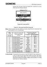
Page 72: ...following tables using the respective mating half contained in the attached plastic bag on the Phase Drive PCB The connectors must be wired as follows Ensure 10mm of wire insulation is stripped back Make sure that the connector is fully undone open before inserting the stripped wire end Insert the stripped wire end fully to the back stop Firmly tighten the connector s terminal screw ensuring that ...

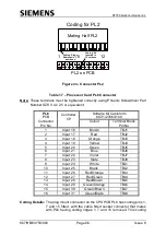
Page 73: ...2 and 15 fitted with the cable fitted socket connector that mates with PL6 having coding pins 1 and 16 fitted This coding prevent the incorrect connection between PL6 and PL7 For more details see the following diagram PL6 Mating Half PL6 16 1 2 15 PCB Table 7 Phase Drive PL7 Connector PL7 Pin No Signal Phase Drive O P Softwire kit Cableform 667 1 27877 000 Colour Ident 1 Red Phase C Unmonitored Re...

Page 74: ...r that mates with PL7 having coding pins 2 and 15 fitted This coding prevent the incorrect connection between PL7 and PL6 For more details see the following diagram PL7 Mating Half PL7 16 1 2 15 PCB Table 8 Phase Drive PL8 Connector for ST750 Phase Driver PCB 6 Phase PL8 Pin No Signal Phase Drive O P Softwire kit Cableform 667 1 27877 050 Colour Ident 1 Red Phase 5 Unmonitored Red RED5 2 Amber Pha...

Page 75: ...or ST750LED Phase Driver PCB PL8 Pin No Signal Phase Drive O P Softwire kit Cableform 667 1 32756 000 Colour Ident 1 Monitored Red Phase A RLM Channel 3 Red RA3 2 Monitored Red Phase A RLM Channel 4 Red RA4 Coding Details This connector has no coding element as it is the only 2 way connector ...

Page 76: ...and Monitors RAU RA1 GA2 YA2 RA2 YB GB RB Vehicle Supply 240v G A R Ped Supply 240 48V R G LMU RLM LMU RLM LMU ONLY LMU ONLY W 7 8 36 40 Phase A Phase B Phase C Phase D Vehicle RLM Channel 2 Vehicle RLM Channel 1 Vehicle RLM Channel 3 Vehicle RLM Channel 4 RLM RLM 35 39 Vehicle RLM Channel 3 Vehicle RLM Channel 4 Current sensor number in this case sensor 6 GRN5 YLW5 RED5 Vehicle Supply 240v G A R ...

Page 77: ...el 1 Vehicle RLM Channel 2 38 A G R PL7 LMU RLM LMU RLM RAU RA1 YA1 GA1 RA2 YA2 GA2 7 8 G W LMU only RB Red Man GB Green Man YB Wait LMU only Phase C Phase D Vehicle Supply 230V Triacs and Monitors Pedestrian Supply 230 48V Wait Supply 48V 36 R Triacs and Monitors Vehicle RLM Channel 1 Vehicle RLM Channel 2 40 RLM PL8 RLM 33 37 RA3 Vehicle RLM Channel 3 RA4 Vehicle RLM Channel 4 No external RLM on...

Page 78: ...kit Cableform 667 1 27864 000 Colour Ident TB1 14 48V Lamp Supply Return Orange None 6 15 48V Lamp Supply Return See note 2 16 48V Lamp Supply Return See note 2 17 48V Lamp Supply Return Orange None 12 Note 1 These neutrals are not used as TB1 block part of cable form is linked between terminals 4 to 12 but these outputs can be used when wired direct in an ST750 cabinet installation Note 2 These 4...

Page 79: ...for details SK2 Pin No Softwire kit Cableform 667 1 27868 002 Connection 1 2 3 Short to pin 6 4 Short to pin 5 5 Short to pin 4 6 Short to pin 3 7 8 9 10 Table 12 Phase Drive SK2 48V Dimming Connections Normally the ST750 in its own cabinet is fitted with the cable 667 1 27868 000 described below see also Figure 28 SK2 Pin No 48V Dimming Transformer s I P Softwire kit Cableform 667 1 27868 000 Col...

Page 80: ...Note 2 The Screen SCR and 48V Return connections on the Dimming Transformer need to be linked together and connected to the Earth Star point in the controller cabinet with a length of yellow green wire Coding Details Connector SK2 has no coding elements as it is the only 10 way connector and can only be inserted one way Table 13 Phase Drive PL5 Connector PL5 Pin No External Lamp Monitoring Sensors...

Page 81: ...associated slot of the IDC board mounted 16 way connector The pin positions 1 2 19 20 on the Berg connector are not used for wiring purposes but are used to provide a stop for the IDC board mounted connector locking levers See the following diagram PCB Mounted IDC Connector Free Standing Berg Connector Pin 1 Four Shaded Pin Positions are not used Coding Slot Coding Flange Connector PL5 and its Mat...

Page 82: ...signals at 230V should be wound around the toroid so the cable passes through the centre twice N B This includes vehicle aspects as well as pedestrian aspects All drive cables supplying signals at 48V should only pass through the centre of the toroid once 5 11 2 ST750 CPU PCB Terminal Blocks When installing in an ST750 cabinet wire the intersection cables directly to the specified connector in the...

Page 83: ...ector Pin No Controller Isolated O P Tactile and Audible Circuits Softwire Kit Cableform 667 1 27863 100 Colour Terminal Block Pin No 1 O P 88 Common Brown TBX1 2 O P 88 Closed Contact Red TBX2 3 O P 89 Common Orange TBX3 4 O P 89 Closed Contact Yellow TBX4 5 O P 90 Common Green TBX5 6 O P 90 Closed Contact Blue TBX6 7 O P 90 Open Contact Not used 8 O P 91 Common Slate TBX7 9 O P 91 Closed Contact...

Page 84: ...27863 100 Colour Terminal Block Pin No 1 Input 0 Brown TBG1 2 Input 1 Red TBG2 3 Input 2 Orange TBG3 4 Input 3 Yellow TBG4 5 Input 4 Green TBG5 6 Input 5 Blue TBG6 7 Input 6 Violet TBG7 8 Input 7 Slate TBG8 9 Input 8 White TBH1 10 Input 9 Black TBH2 11 Input 10 Red Orange TBH3 12 Input 11 Red Green TBH4 13 Input 12 Red Brown TBH5 14 Input 13 Green Orange TBH6 15 Input 14 Green Brown TBH7 16 Input ...

Page 85: ...63 100 Colour Terminal Block Pin No 1 O P 92 Common Brown TBY1 2 O P 92 Closed Contact Red TBY2 3 O P 93 Common Orange TBY3 4 O P 93 Closed Contact Yellow TBY4 5 O P 94 Common Green TBY5 6 O P 94 Closed Contact Blue TBY6 7 O P 94 Open Contact Not used 8 O P 95 Common Slate TBY7 9 O P 95 Closed Contact White TBY8 10 O P 95 Open Contact Not used 11 Tactile Phase D Red Orange TBY10 12 Audible Phase D...

Page 86: ... 100 Colour Terminal Block Pin No 1 Input 16 Brown TBJ1 2 Input 17 Red TBJ2 3 Input 18 Orange TBJ3 4 Input 19 Yellow TBJ4 5 Input 20 Green TBJ5 6 Input 21 Blue TBJ6 7 Input 22 Violet TBJ7 8 Input 23 Slate TBJ8 9 Input 24 White TBL1 10 Input 25 Black TBL2 11 Input 26 Red Orange TBL3 12 Input 27 Red Green TBL4 13 Input 28 Red Brown TBL5 14 Input 29 Green Orange TBL6 15 Input 30 Green Brown TBL7 16 I...

Page 87: ...ssembly does not cover regulatory signs and their associated monitoring There is a fuse position labelled F3 Detector which could be used to supply regulatory signs if required Their monitoring would require standard current coils to be connected to the external analogue inputs 5 13 PCB SWITCHES FUSES LINKS AND FIRMWARE The switches fuses and link settings are related to the hardware options their...

Page 88: ...L12 Phase Control Bus PL4 Manual Panel Connector PL1 Controller O P 88 to 91 Controller O P 92 to 95 Controller I P 0 to 15 Controller I P 16 to 31 Detector Supply Extended System Bus PL11 S1 S3 S2 S4 PP SE WD EPLD Phase Bus Processor Firmware Main Processor Firmware 1st 2nd Main Processor Phase LED Displays A B C D E F Status LED Displays LK1 Switches and Link Setting Positions RS232 Handset Port...

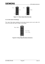
Page 89: ...ing the right combination of S4 switches to the off position The set up is detailed as follows Figure 36 Flash Rate Settings 5 13 1 2 DIL Switch S2 S3 Settings For use in the UK these switches should be set to the OFF position The settings are shown in Figure 37 For Non UK versions each of the six phases can be set individually to flash either Red using S2 or Amber using S3 or both Red and Amber w...

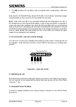
Page 90: ...8 not used Figure 37 Phase Output Flash Selection 5 13 1 3 DIL Switch S1 Settings The value of the series resistance for the relay contacts can be set to either 182 ohms or 22 ohms and is set on switch S1 as follows 5 S1 ON OFF 6 7 8 1 2 3 4 Relay Output ON 22 Ohms OFF 182 Ohms Figure 38 Relay Output Resistance Selection ...

Page 91: ...cle Ambers F10 and F11 are Pedestrian Red Green Ribbon cable connected to 64 way connector on Controller Board F1 F4 F11 F10 F3 F2 F9 F8 F7 F6 External Analogue I Ps Connector Current Coil Phase 1 2 Drive O Ps Connector Phase 5 6 Drive O Ps Connector ST700 PSU Connector MAP 140 PSU Connector Mains I P Connector External Mains and 48V Connections SK1 1 16 PL2 Mains I P 24V O P Dimming Transformer C...

Page 92: ... service personnel inserting an extra fuse and thus causing damage to occur to the ST750 5 13 2 2 Blue and Red Handbag Links Settings The output voltage monitoring circuits for the Pedestrian Red and Pedestrian Green can be set to monitor either 230V or 48V Inserting the correct coloured handbag links on the board sets the voltages for the Monitoring circuit The positions and colours are as follow...

Page 93: ...ey fit into PCB mounted sockets and use spring clips in the socket to make the connection and fit These spring clips also retain the link to the PCB the contacts are gold plated for low resistance and reliability 5 13 2 3 Links LK1 LK2 LK3 and LK4 Settings The links LK1 to LK4 have handbag links fitted as shown below These should not be changed Note that later versions of this PCB do not have any ...

Page 94: ...le in order to meet the particular requirements of an area or of one particular site These configurations need to be customised for particular installations using the handset and the information in the special instructions of the configuration printout The commands to customise the ST750 are described in the Handset Handbook and in the Special Instructions These allow facilities such as kerbside a...

Page 95: ...r Information Handbook Set up the date and time Check that the Lamp Monitor has correctly learnt all the lamp loads using the KML and KEL handset commands described in the Controller Handset Handbook Check that there are no unexplained errors in the fault log This completes the testing and the site should be ready for Customer acceptance 5 16 ST750 START UP SEQUENCE When the ST750 is initially pow...

Page 96: ...cribed in the Handset Handbook 5 17 COMMON RETURNS FOR PUSH BUTTON For the connections for the common returns see the following drawings ST750 in small outer case 667 CC 29000 002 ST750 in large outer case 667 CC 29000 003 5 18 COMMON RETURNS FOR DETECTORS For the connections for the common returns see the following drawings ST750 in small outer case 667 CC 29000 002 ST750 in large outer case 667 ...

Page 97: ...me examples are ST800 T400S T400L GEC110 125 CST McQue T110 T500P GEC125 in 25 Case Microsense Midi The procedure for each type of Cabinet depends largely on the type and condition of the existing equipment For this reason it is not possible to define in detail exactly what should be undertaken but generally the procedure follows that defined in sections 5 1 to 5 14 For some Cabinets conversion ki...

Page 98: ...s suggested that these procedures be performed in the order listed Examine the cabinet and equipment mounting frame for serious damage The cabinet would normally only be replaced if it has been damaged to the extent that its security has been breached or that water or dirt is entering Check the base seal for integrity If damaged perform repair or advise customer dependent on the terms of the contr...

Page 99: ... and cableforms particularly ribbon cables for damage Replace or re route as appropriate The battery on the ST750 CPU PCB must be replaced if it has failed Any replacement battery should be suitably marked with an appropriate date label Having done this the ST750 records should be updated accordingly The following tests require the ST750 to be powered and running normally Tests of the Voltage Drop...

Page 100: ...maged the affected area should be filled with sand and re sealed For details see section 5 10 7 3 ROUTINE SETUP CHECK Check that the real time clock is set correctly as described in the Controller Handset Handbook Use the time of day TOD command to check that the real time clock is running the correct time A true measurement of the accuracy of the real time clock can only be gained if the clock wi...

Page 101: ... make a note of the PCB and pin number in the Controller Visit Log Book as the ribbon backplanes may have been damaged b Check any ICs that are mounted in sockets and ensure that they are the correct ones for the position and are securely fitted Refer to the works specification for further details A problem with a loose fitting IC or use of an incorrect one can usually be rectified easily without ...

Page 102: ...ue Refer to the Works Order Specification for details The mounting pillars on the CPU are a nylon clip type and only require the clipping mechanism to be released to allow the board to be removed The pillars are retained on the hinge plate by means of an integral clipping mechanism on the other end When the CPU is replaced make sure that the clipping mechanism of the mounting pillar is fully engag...

Page 103: ...bed in section 5 13 Reconnect PL1 PL6 PL7 PL8 SK1 SK2 and the earth wires Replace the hinged front plate holding the CPU PCB and if fitted the I O or OTU PCB Replace all the cables to the CPU Clip the earth lead to the front plate Restore power to the ST750 Note The new Power Phase assembly is supplied with a chassis door fitted It is not necessary to replace the door when the Phase Drive PCB has ...

Page 104: ...placement of the board 7 5 REPLACEMENT OF MAINS POWER SUPPLY UNIT The spare Mains Power unit is provided as part of the Power Phase Assembly It is not necessary to replace the whole assembly if the power unit has failed providing the failure has not damaged other components The Mains PSU may be removed once the following have been carried out The Mains to the ST750 Rack Assembly has been isolated ...

Page 105: ...ST750 GENERAL HANDBOOK 667 HB 33750 000 Page 105 Issue 6 ...

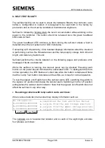
Page 106: ...essages if faults are detected While the self test is running the manual panel can be checked Pressing each button on the panel should illuminate the associated LED To distinguish this from normal operation the LED flashes at a fast rate while the button is depressed Note that the Lamp Test button illuminates all the LEDs as it does for normal operation To test the signals on off switch and the ca...

Page 107: ...M FAULT PRG PROM FAULT XTL FAULT DPR R W FAULT All the above faults point to problems internally on the main processor card Checks communications with the secondary phase bus processor P Bus CPU If the processor cannot be detected then the self test will wait indefinitely at this point with the red system error LED illuminated Check that the processor and its firmware are fitted Examines the lamp ...

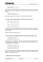
Page 108: ...e and negative mains peaks for each of the two test voltages 0V and 2 5V are displayed on the handset Ideally the values should be 0 and 128 Checks that the lamp supply and voltage monitors are detecting no mains L Supply Off 240V L Supply Stuck On If a lamp supply is being detected then this implies that the lamp supply relays are all switched on very unlikely or the lamp supply monitoring transf...

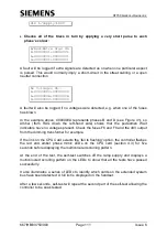
Page 109: ...irm that the self test may switch on the lamp supply and continue its tests After the level 3 button is pressed self test switches on the lamp supply Towards the end of this second sequence of tests it tests all the triacs by switching each one on in turn for a very short period of time If standard HI 12V halogen lamps are used with a transformer in the signal head then this pulse will not be seen...

Page 110: ...on unit Also check that the dim connector SK2 is connected N B Links are required on this connector even if no transformer is required Checks that each lamp supply relay can switch off the lamp supply independently SSR Fault Relay A Fault Relay B Fault Failure of any of these tests implies that the relay is not switching off i e that it is either welded closed or the control signals from the main ...

Page 111: ...ure 41 so Amber from RAG down the left hand side shows that the pedestrian Wait indicators have no voltages present Check the fuses F6 and F8 and the 48V output from the dimming transformer for example If the link on the CPU Card selects the fail to flashing option the controller flashes the red and amber phase mimic LEDs on the CPU card section 4 3 for five seconds before displaying the multicolo...

Page 112: ... ST900 CAB GREY 667 1 33750 224 ST750 UK SINGLE PED IN T400S CAB GREY 667 1 33750 010 ST750 UK SINGLE PED IN T400S CAB BLK 667 1 33750 011 ST750 UK DUAL PED IN T400S CAB GREY 667 1 33750 020 ST750 UK DUAL PED IN T400S CAB BLK 667 1 33750 021 ST750 LED UK SINGLE PED IN T400S CAB GREY 667 1 33750 210 ST750 LED UK DUAL PED IN T400S CAB GREY 667 1 33750 220 ST750 UK RACK SINGLE PED ASSY 667 1 33750 51...

Page 113: ...32755 754 11 Swing Frame 667 1 27087 411 19 Swing Frame 667 1 27087 000 11 3U Detector Rack 667 1 20690 000 19 3U Detector Rack 667 1 20690 001 Freestanding TC12 OTU in 11 5U Rack 667 1 22691 001 Freestanding TC12 OTU in 19 5U Rack 667 1 22691 002 See 667 HB 32921 007 in Section 1 3 2 for further details A 2 SPARES LIST Listed here are the parts that should be used when replacing components In add...

Page 114: ...ses incl audio drives 667 1 27877 000 Phase Softwire kit 5 6 phases incl audio drives 667 1 27877 050 A 2 4 OTHER SPARES Lithium 3V Battery 418 4 39829 000 Isolator Locking KOP 667 1 21923 001 Manual Panel signs on off only 667 1 27056 010 CET Bar Kit 667 1 27845 000 Door Switch KOP 667 1 27852 000 Detector Mounting Frame 667 1 33770 000 Manual Panel Gasket 667 7 27129 000 Sealant Stool to Case 99...

Page 115: ...pply Fuse 518 4 90301 013 10A cartridge fuse 20mm x 5mm marked F7 on Phase Drive PCB 230V R G Supply Fuse 518 4 90301 013 10A cartridge fuse 20mm x 5mm marked F10 on Phase Drive PCB 48V R G Supply Fuse 518 4 90301 013 10A cartridge fuse 20mm x 5mm marked F11 on Phase Drive PCB 230V Amb Wait Supply Fuse 518 4 90301 013 10A cartridge fuse 20mm x 5mm marked F8 on Phase Drive PCB 48V Wait Supply Fuse ...

Page 116: ...ST750 GENERAL HANDBOOK 667 HB 33750 000 Page 116 Issue 6 LAST PAGE OF THE ST750 GENERAL HANDBOOK ...

Reviews: