ST750
G
ENERAL
H
ANDBOOK
667/HB/33750/000
Page 49
Issue 6
4.3.2 Signal LED Group
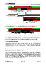
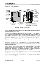
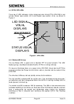
These LEDs are in groups of three, one for each traffic phase A to F. Each group
has a red at the top, amber in the middle and green at the bottom (see View of
Phase ‘F’ in Figure 9) to represent a set of traffic lights. They provide visual
representation of the state of the red, amber and green drives for their respective
phase.
4.4 Master Switch Assembly
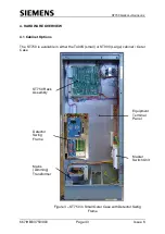
The Master Switch Assembly is mounted in the bottom right hand corner of the
controller, refer to Figure 3
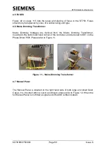
With reference to Figure 10 the mains supply voltage is applied to the main ON/OFF
63A circuit breaker, within the Master Switch Assembly, for onward supply to the
ST750 Traffic Controller.
The live supply wire is taken from the main ON/OFF mini circuit breaker and applied
to a Master 20A Mini Circuit Breaker.
The output from the 20A Mini Circuit Breaker is applied a 5A fuse. Output from the
fuse is applied to 300mA Residual Current Device (RCD) for onwards distribution to
the two main outlet sockets
.
Space is provided on the Master Switch Assembly to fit
an additional 5A fuse; to be utilised as an auxiliary power supply. Controller mains
power Live is taken from the 20A Mini Circuit Breaker and applied to PL1 on the
Phase Drive PCB.
Figure 10
– Master Switch Assembly
63A
Main
ON/OFF
Switch
20A Mini
Circuit
Breaker
5A
Fuse
300 mA
RCD
Position
for
additional
5A Fuse

