background image

Mobility, Intelligent Traffic Systems

Sopers Lane, Poole, Dorset, BH17 7ER

Security 

classification  Unrestricted

Page

41 of 92

Version

3

Status

Issued

Last Editor

Alan Doyle

Date

05-Oct-2017

Document Name

Stratos Outstation General and ICM Handbook  Document No.  667/HB/52250/000

Copyright © Siemens plc 2014.  All Rights Reserved.    Mobility and Logistics is a division of Siemens Plc

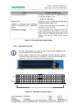
Fault/Notification Table

(& system log) message

Possible Cause & Remedy

‘Card 15, Support Battery
Charger Forced Off’

Battery charger has been disabled by the user. Pin 6 of the
‘General functions connector’ (located at rear of the PSU
board) has been taken to 0V. This may be required if an
external battery is being used.

– to enable the charger ensure pin 6 is left unconnected
(floating).

‘Card 15, Support Battery
Charger Disabled –
Temperature Out of Range’

Ambient temperature is outside the battery operation range
(-20°C to +60°C). The battery will continue to be used to
provide backup power in the event of a mains power
failure, however hold up cannot be guaranteed as the
battery charge will not be maintained.

If the ambient temperature is comfortably within the battery
operation range, this suggests there is a hardware fault on
the PSU board.

– Check if the PSU board has also logged a ‘Hardware
error’. Replace the PSU board.

‘Card 15, Support Battery
Capacity Low (xx%)

The 30 day battery capacity test failed to complete. The
expected battery voltage was not maintained for greater
than the configured ‘Battery Capacity Low threshold’ value.
This indicates the battery capacity has reduced
significantly*

3

.

As a guide:

– If the estimated battery capacity is less than 10% the
battery should be replaced immediately, as it is unlikely the
battery will be able to provide backup power for the
required 1 minute period.

– If the estimated battery capacity is between 10%-25%,
the user is advised to replace the battery at the next
convenient opportunity.

‘Card 15, Support Battery
On-load Voltage Drop x.xV

The 30 day on-load test failed. The On-load voltage drop is
greater than the configured ‘Battery Voltage Drop
Threshold’ value. This indicates the battery capacity has
reduced significantly*

3

The battery capacity test result provides the best indication
of when the battery needs to be replaced. The on-load test
result can be used in conjunction to provide further
assurance of when the battery should be replaced. A
voltage drop greater than 1.5V would support the need to
replace the battery immediately.

Table 16 – Inbuilt battery backup troubleshooting

Summary of Contents for Stratos Outstation

Page 1: ...OOL All PAPER COPIES ARE DEEMED UNCONTROLLED COPIES Prepared By Checked and Released Division BU Mobility Intelligent Traffic Systems Mobility Intelligent Traffic Systems Department Engineering Engineering Name C Rabe J Ballantine J Hollingworth K Napper D A Martin Function Lead Engineer Engineering Manager Date October 2017 October 2017 COPYRIGHT STATEMENT The information contained herein is the ...

Page 2: ...tricity at Work Regulations 1989 or the relevant local state and government regulations Such personnel must take heed of all relevant notes cautions and warnings in this Handbook and any other Document or Handbook associated with the equipment including but not restricted to the following The equipment must be correctly connected to the specified incoming power supply The equipment must be disconn...

Page 3: ...acid battery depending on variant type Do not short circuit puncture take apart incinerate crush immerse force discharge ingest or expose to temperatures above the declared operating temperature range of the product otherwise there is a risk of fire or explosion Batteries should be handled and stored carefully to avoid short circuits Do not store in disorderly fashion or allow metal objects to be ...

Page 4: ...st Editor Alan Doyle Date 05 Oct 2017 Document Name Stratos Outstation General and ICM Handbook Document No 667 HB 52250 000 Copyright Siemens plc 2014 All Rights Reserved Mobility and Logistics is a division of Siemens Plc Change History Issue Change Reference Date 1 First Issued Dec 2014 2 Updates for Stratos Feb Nov 2016 3 TS008492 Mar Sep 2017 ...

Page 5: ...rface with Controller Monitoring 15 2 3 3 Freestanding Interface to Controller without Monitoring 15 3 Product Features Description 16 3 1 UTMC OTU 16 3 2 MOVA Microprocessor Optimised Vehicle Actuation 16 3 3 Controller Monitor 16 3 4 Intelligent Parking 16 3 5 Digital Input Output 16 3 6 Backup Power for Last Gasp Dial 17 3 7 Clock System 17 3 8 Self Test Facility 17 3 9 Lamp Supply Monitoring 1...

Page 6: ...ard 43 4 8 1 I O LEDs 46 4 8 2 I O Faults 46 4 8 3 Connector Pinouts 47 4 8 4 Changing Fuses 49 4 8 5 I O Board Rotary Address Switch 49 4 8 6 Replacing the I O Board 49 4 8 7 I O Board Kits Assembly 49 4 8 8 TC12 Adaptor Board 50 4 9 The Intelligent Detector Backplane 51 4 10 Single Detector Backplane 53 4 11 Racks 54 5 Installation And Commissioning 55 5 1 Pre Requisites 55 5 1 1 Documentation 5...

Page 7: ...egral Stratos Outstation Connectivity 14 Figure 2 Typical Freestanding Stratos Connectivity with Monitoring 15 Figure 3 Typical Freestanding Stratos Outstation Connectivity 15 Figure 4 Example Roadside Setup 22 Figure 5 Stratos Outstation System Overview 26 Figure 6 CPU Board Front Rear Connections 28 Figure 7 CPU Board Layout 28 Figure 8 PSU Board 33 Figure 9 PSU Board Layout 33 Figure 10 PSU Boa...

Page 8: ... PSU board fault troubleshooting 36 Table 11 PSU Inputs and Outputs 15 Way 3 5mm pitch 36 Table 12 Lamp Supply General Functions Connector Pinout 37 Table 13 General Functions Detailed Description 38 Table 14 PSU Board Fuses 38 Table 15 PSU Board Switches 39 Table 16 Inbuilt battery backup troubleshooting 41 Table 18 PSU I O Board LED States 46 Table 19 I O board fault troubleshooting 47 Table 20 ...
Page 9: ... process Section 7 covers maintenance 1 2 Contact Us If you have any comments on this handbook need any further information or need to contact Poole Engineering you can contact us at trafficwebmaster stc siemens com 1 3 Related Documents 667 HU 46000 000 User Interface Handbook ST950 Stratos Outstation 667 HB 46000 003 MOVA 7 Handbook ST950 Stratos Outstation 667 HB 46000 004 UTMC OTU Handbook ST9...

Page 10: ...a Low Voltage ESP Enhanced Serial Port GSPI Siemens proprietary protocol General Serial Peripheral Interface GPS Global Positioning System HTTP Hypertext Transfer Protocol HTTPS HTTP Secure HPU ST900 950ELV High Power Unit IDB Intelligent Detector Backplane I O Input Output IP Internet Protocol LED Light Emitting Diode LV Low Voltage Mains mA milliamps MDU ST800 900 950 Mains Distribution Unit MOV...

Page 11: ... On written request within three years from the date of product purchase and against payment of our expenses we will supply source code in line with the terms of the applicable license For this please contact us at Open Source Clearing Product Development Engineering Department Siemens Mobility Intelligent Traffic Systems Sopers Lane Poole Dorset BH17 7ER UK Generally these embedded free software ...

Page 12: ... Storage device Known as the Heart contains restore points for the Outstation firmware backups configuration data logs etc allowing fast repair by board replacement and Mass Storage device transfer Extended features licensed through encrypted license card Two Integrated Ethernet interfaces Four USB Host interfaces for memory devices license card readers WiFi dongle optional RS232 handset adaptor O...

Page 13: ...combination of the two The interface summary for each controller type is given in the following table Supplier Controller RS232 Protocol Controller Monitoring Interfac e type Siemens ST950 ESP Semi integral see 2 3 1 ST900 ESP P ST800 ESP P ST750 ESP P ST700 ESP P T400 ASCII 7bit P Free Standin g see 2 3 2 and 2 3 3 T500 ASCII 7bit Microsense Telent MPC ASCII 7bit MTC ASCII 7bit Sentinel ASCII 7bi...

Page 14: ...tates as configured by IC4 for use as UTC SCOOT detectors and MOVA detectors Faults for display on outstation fault table and reporting to Stratos 2 Controller Log for display on outstation web interface 2 IC4 configuration upload 3 Remote handset text 1 If connecting to ST950 controller identification and scanning should be disabled and Enhanced Serial Protocol should be enabled These can be setu...

Page 15: ...with Monitoring As a free standing interface but with Stratos capability to monitor faults via the serial interface see 3 3 Controller Monitor 2 3 3 Freestanding Interface to Controller without Monitoring Figure 3 Typical Freestanding Stratos Outstation Connectivity The RS232 serial cable is used only for remote handset The following data is transferred between the controller and the outstation vi...

Page 16: ...tor The Controller Monitoring application identifies and monitors a connected controller Detected conditions are raised in the Fault or Notification Table as appropriate Where the Outstation is connected to Stratos these conditions are also reported to Stratos The Controller Monitor application requires very little configuration and in most cases the default configuration will be appropriate The c...

Page 17: ...protects and maximizes battery life For more information see section 4 7 and the IP Router Installation Guide 667 CI 45025 000 3 7 Clock System The software real time clock that controls the system records seconds minutes hours day month year and day of week The clock also has a standby RTC circuit which remains supported during power failures for up to 48 Hours An external RTC backup input on the...

Page 18: ...trol of all areas necessary for day to day maintenance including System Status and Configuration System Log Fault Table A command line text interface is also available e g for use with remote terminals or handset connection along with a simple text based menu system to allow straightforward maintenance without the need for knowledge of handset commands or use of a PC The User Interface is describe...

Page 19: ...00 3 13 Site Log The Site Log records significant site events System firmware update is automatically recorded in the site log It is also possible for the user to create text records either with or without a file attachment Attachments can be useful to record site details through diagrams photographs documents etc For more information see the User Interface Handbook 667 HU 46000 000 3 14 Remote Re...

Page 20: ...b page For more information see the User Interface Handbook 667 HU 46000 000 3 17 Licensing Certain features within the Stratos Outstation are licensed Licences are distributed and held on Smart Cards For storage on the unit a SIM size Smart Card is fitted in the Smart Card holder on the CPU Board Licences are easily installed onto a Stratos Outstation either by mounting the licence Smart Card on ...

Page 21: ... the CPU Board The formatting of the card is such that it is not readable in a PC There are no user files accessible on the card Backups are created and written to the Heart periodically usually at 00 30am but this can be changed if required Backups can also be created and saved on demand For more information see the User Interface Handbook 667 HU 46000 000 3 19 Firmware Update Most of the firmwar...

Page 22: ...ings to a single target IP address This feature allows specific limited remote access to network equipment via the Gemini using specific ports without exposing the devices to the whole wan side of the external network that the Gemini is connected to The application requires the server port mappings and ip address of the target machine These can be entered via the terminal interface cfgitem command...

Page 23: ...nt Name Stratos Outstation General and ICM Handbook Document No 667 HB 52250 000 Copyright Siemens plc 2014 All Rights Reserved Mobility and Logistics is a division of Siemens Plc 3 21 1 1 Ethernet Setup First ensure that the second outstation ethernet IP address is set to an address on the target machine roadside subnet The second Ethernet port is the upper of the two ports on the CPU card ...

Page 24: ...Stratos Outstation General and ICM Handbook Document No 667 HB 52250 000 Copyright Siemens plc 2014 All Rights Reserved Mobility and Logistics is a division of Siemens Plc 3 21 1 2 Using the Status and Configuration Web Page Interface Under System Advanced Network TCP Proxy Server select either Proxy Ports to configure the port mappings Or select Target IP Address to configure the target IP addres...

Page 25: ...The items that need to be set are server targetipaddress server proxyports n where the target ip address is of form ww xx yy zz eg server targetipaddress 172 16 41 133 proxyports n ranges from proxyports0 proxyports9 to give potentially 10 port mappings of the form client side port target side port eg server proxyports0 8090 443 The default settings are server proxyports0 8090 443 server targetipa...

Page 26: ... IN OUT GSPI RS422 RJ45 Modem Pwr 2x GSPI RS422 RJ45 2x Ethernet RJ45 2x USB Host USB Slave 2x USB Host CPU Heart SD Card License Reset Top Ethernet Bot 16W 10W IEC Inlet Internal Backup Battery To GSPI IN on next I O Card Top Bottom I O Card 1 I O Card 2 I O Card 3 CPU Card PSU Card 8 Inputs 2 Outputs TR2523 Battery Isolation Switch 110 240V AC Mains Input AC DC Power Supply 110 240V AC Mains Inp...

Page 27: ...ns power fails and the unit enters battery backup mode the power is cut by software to peripherals on the downstream OUT side in order to preserve battery capacity For GSPI peripherals that have a general purpose I O capability e g the PSU board and the IO board their IO is mapped into the CPU board in 8 bit ports for example gspi1 in 0 For details on the I O mapping process refer to the UTMC OTU ...

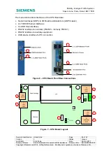
Page 28: ...00 Copyright Siemens plc 2014 All Rights Reserved Mobility and Logistics is a division of Siemens Plc The main external data interfaces of the CPU Board are Serial Interfaces GSPI to I O Boards and detectors GSPI master 2x 10 100 Ethernet Interfaces 4x USB Host interfaces RS232 interface to controller TR2523 formerly TR0141 RS232 interface to auxiliary equipment USB device interface for PC connect...

Page 29: ...2 x 10 100 Ethernet Ports 1st port is closest to PCB Double RJ45 5 RS232 Port TR2523 16 way IDC boxed header 6 RS232 Port Modem GPS etc 10 way IDC boxed header 7 USB Handset Port USB Type B 8 2 x USB Host Ports front Double USB Type A Table 5 CPU Board Connector Functions and Types Pin Function 1 24V DC input Power for CPU board when no PSU board is used 2 0V 3 Switched 24V Nominal Modem supply ou...

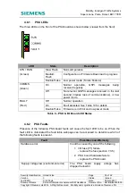
Page 30: ...ernet interfaces Top and Bottom Modem Power inboard On Indicates that the Modem Power is on Off Indicates that the Modem Power is off Restricted mode is similar to safe mode on a PC where the user can access the unit to examine logs diagnose problems and perform firmware updates Table 7 CPU Board LED States 4 4 2 Changing the Heart The heart should only ever need to be replaced under the following...

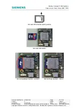
Page 31: ...t Editor Alan Doyle Date 05 Oct 2017 Document Name Stratos Outstation General and ICM Handbook Document No 667 HB 52250 000 Copyright Siemens plc 2014 All Rights Reserved Mobility and Logistics is a division of Siemens Plc SD card Write Enable switch position SD Card Orientation û SD card partially inserted incorrect ü SD card fully inserted correct ...

Page 32: ...e card holder 5 Insert the card in to the holder as shown contact side towards board and chamfered edge towards bottom of board 6 Lower the holder and return the locking ring to the locked position For License installation see the User Interface Handbook 667 HU 46000 000 4 4 4 Replacing the CPU card Should the CPU card need to be replaced see section 7 3 1 for details 4 5 USB to 25 Way D Type Adap...

Page 33: ...oard provides power for the system and provides application specific hardware modules to support specific functions This board acts as a GSPI device to allow the CPU board to communicate with it The main functions of the PSU Board are Logic rail power supplies Basic 8 input 2 output TR2523 I O Mains monitoring and Zero Cross Over timer ZXO Lamp Supply voltage monitoring ELV LV Backup battery contr...

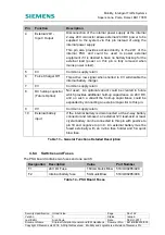
Page 34: ... a Stratos Outstation provides power on the GSPI Bus When in battery backed mode the power is cut to the downstream peripherals OUT side See section 4 2 for more information Double RJ45 2 LV ELV Lamp Supply Monitor Input See Table 12 for pinout 2 way 5 08mm pitch Phoenix See Appendix B for part No 3 General functions See Table 13 for pinout 10 way 3 5mm pitch Phoenix See Appendix B for part No 4 A...

Page 35: ...e COMMS Green On Normal operation GSPI messages being received regularly Off No relevant GSPI messages received in the last second implies loss of communications or low power mode FAULT Red Off Normal operation On Fault detected See Table 10 for details Double Pulse Firmware is in Error and low power mode Table 9 PSU I O Board LED States 4 6 2 PSU Faults Presence of the following PSU board faults ...

Page 36: ...chdog Failure S W general error Initialisation failure Unlikely to occur If observed report to Poole Engineering see section 1 2 Power cycle the Gemini3 unit if possible to attempt to remove the fault Table 10 PSU board fault troubleshooting 4 6 3 Pinouts PSU Inputs and Outputs 15 Way 3 5mm pitch Pin Function Card Port Bit ID Loom Colours 667 1 30607 000 15 Input 8 Gspi15 in 0 8 Brown Green 14 Inp...

Page 37: ... Connector Pinout The individual pin functions are fully described in Table 13 below A basic description of the pinouts for all PSU connectors can be found on the battery cover Pin Function Description 1 RTC Out This provides a Power feed from the PSUs internal backup battery that can be connected to the CPU board Optional RTC supply input on the modem power connector pin 4 to allow the RTC backup...

Page 38: ... 0V Common supply return 6 Force Charger Off This active low signal when shorted to 0V will disable the internal battery charger 7 0V Common supply return 8 DC holdup capacitor Future Option Not used An optional variant could be created in future which provides additional hold up capacitance on 24V DC and on such a variant the hold up capacitance could be expanded by connecting an external capacit...

Page 39: ... as routine maintenance typically every 3 5 years under normal circumstances to ensure that the backup time is adequate for instation communications during a power failure The battery test see below can be used to determine exactly when to replace the battery If the application demands backup at extremes of temperature outside 20 C to 60 C then an external battery can be connected to the Power sup...

Page 40: ...ng capacity of the battery Therefore the capacity test result either shows a pass or the estimated remaining fully charged capacity where 25 suggests the battery is only capable of retaining a quarter of the charge of a brand new battery The on load impedance test compares the unloaded and loaded battery voltage This battery voltage drop is compared against the user configured threshold value The ...

Page 41: ... this suggests there is a hardware fault on the PSU board Check if the PSU board has also logged a Hardware error Replace the PSU board Card 15 Support Battery Capacity Low xx The 30 day battery capacity test failed to complete The expected battery voltage was not maintained for greater than the configured Battery Capacity Low threshold value This indicates the battery capacity has reduced signifi...

Page 42: ...ry self tests are inhibited and do not run Note 2 The test is delayed if the temperature is outside the battery range or if there has been a mains failure in the previous 12 hours Note 3 It is not possible to precisely specify the point at which the battery is deemed faulty and should be replaced The battery capacity and on load test results allow the user to determine what constitutes a faulty ba...

Page 43: ...connector is compatible with Gemini2 Bus MOVA I O board pinout GSPI pass through connection for daisy chaining of GSPI peripherals Powered by the GSPI Connection Inputs The I O board inputs are compliant to TR2523 2005 as follows Closed Circuit is indicated when a resistance of 250 Ohms or less is present across the input terminals Open Circuit is indicated when a resistance of 100K Ohms or greate...

Page 44: ...ts are volt free fully isolated outputs that are compliant with TR2523 2005 as follows Maximum ON resistance of 185Ohms When ON an output is rated at 50mA maximum When OFF and output will withstand 75V DC continuous When OFF and output will present a resistance of greater than 100K Ohms The COMMON NORMALLY OPEN and NORMALLY CLOSED contacts of each output are isolated from any other The relay conta...

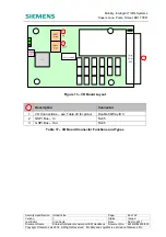
Page 45: ...17 Document Name Stratos Outstation General and ICM Handbook Document No 667 HB 52250 000 Copyright Siemens plc 2014 All Rights Reserved Mobility and Logistics is a division of Siemens Plc Figure 13 I O Board Layout Description Connector 1 I O Connections see Table 20 for pinout Double 50Way IDC 2 GSPI Bus In RJ45 3 GSPI Bus Out RJ45 Table 17 I O Board Connector Functions and Types ...

Page 46: ...en On Normal operation GSPI messages being received regularly Off No relevant GSPI messages received in the last second implies loss of communications or low power mode FAULT Red Off Normal operation On Fault detected see fault section for details of possible faults Double Pulse Firmware is in Error and low power mode Table 18 PSU I O Board LED States 4 8 2 I O Faults Presence of the following I O...

Page 47: ... to occur If observed report to Poole Engineering see section 1 2 Power cycle the Gemini3 unit if possible to attempt to remove the fault GSPI Address Changed The board address has changed but the new address will not take effect until the next board reset All board addresses should be set as desired and then the whole system power cycled Table 19 I O board fault troubleshooting 4 8 3 Connector Pi...
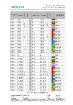
Page 48: ...3 3 Green Orange Bottom 20 Input 20 4 Top 20 Input 44 4 Green Brown Bottom 21 Input 21 5 Top 21 Input 45 5 Green Grey Bottom 22 Input 22 6 Top 22 Input 46 6 Brown Grey Bottom 23 Input 23 7 Top 23 Input 47 7 Orange Brown Bottom 24 Input 24 8 Top 24 Input 48 8 Orange Grey Bottom 25 0V Top 25 0V White Bottom 26 0V Top 26 0V White Bottom 27 N O O P 1 gspiX out 6 1 Top 27 N O O P 9 gspiX out 7 1 Blue B...

Page 49: ...GSPI peripheral boards and must be unique The Stratos Outstation PSU board is fixed at address 15 so this address must not be used 4 8 6 Replacing the I O Board Should an I O board need to be replaced see section 7 3 1 for details 4 8 7 I O Board Kits Assembly The Stratos outstation supports a number I O board options as listed below Description Part Number 48 16 I O Board Kit with cable I O card ...

Page 50: ...This is of particularly benefit where a 3rd party controller is involved or there is no enhanced serial link To Gain the Maximum advantage it is essential that a few basic rules are followed The Bit pattern of the Gemini must be the same as that of the TC12 The TC12 word cables should be treated carefully and not disconnected from the controller If the TC12 is also used for the controllers lamp mo...

Page 51: ...etector outputs into I O board inputs and provides a mechanism for terminating the street loop wiring for 16 loops for each backplane fitted Each IDB must be addressed in the same manner as any GSPI I O board as described in Section 4 8 5 The Intelligent Detector Backplane Kit part number is 667 1 32910 950 Whenever detectors are used a separate detector supply kit will be required unless there is...

Page 52: ...ing a system it is important to consider the number of single detectors IDBs and Stratos outstation along with rack size to determine the build format Table 22 below will help in the design phase to define the physical rack space required The function IO mapping for the IDB is shown in Table 21 When configuring the IO mapping in the outstation this table should be consulted Detector Function Card ...

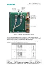
Page 53: ... Card Port Bit ID 4 Loop 1 Detect 5 Loop 2 Detect 6 Loop 3 Detect 7 Loop 4 Detect 8 Not Used GspiX in 2 1 8 1 Detector Reset GspiX out 3 1 2 Detector Reset 2 3 Detector Reset 3 4 Detector Reset 4 Not Used 5 8 Table 21 IDB IO Mapping Note X denotes gspi card number the same as card address 4 10 Single Detector Backplane Loop detectors can be connected using the single detector backplane 667 1 17205...

Page 54: ...he numbers displayed are the maximum that can be fitted into an 11 or 19 rack 11 Rack Combinations Stratos Outstation 1 1 1 1 48 16 I O Board 0 1 2 3 IDB 0 0 0 0 Single Detector 2 2 2 1 19 Rack Combinations Stratos Outstation 1 1 1 1 48 16 I O Board 0 1 2 3 IDB 2 2 2 2 Single Detector 2 1 0 0 TC12 adaptor is the same width as a 48 16 I O board Table 22 Rack Population Guide If the unit is a standa...

Page 55: ...00 000 which provides details of how to connect to the unit and the different user interfaces which are available Please also refer to the various handbooks and quick start guides available as shown in section 1 3 5 1 2 Qualifications Only skilled or instructed personnel with relevant technical knowledge and experience who are also familiar with the safety procedures required when dealing with mod...

Page 56: ...7 1 47180 000 667 4 13296 000 Larger Screened Oyster handset Requires USB to RS232 Handset Adaptor Cable 667 1 47180 000 667 4 13296 002 USB to RS232 Handset adaptor cable for handheld RS232 terminal 667 1 47180 000 USB WiFi Dongle Can be used with WiFi laptop or smart phone 667 1 45966 001 Cabinet Access If the outstation is mounted in a Siemens Traffic Controller one or more of the following wil...

Page 57: ...c OTU Supply Kit 667 1 27121 000 In case there are no spare fused supplies Printed SAT Sheet for completion on site 667 CI 31601 002 Printed OTU MOVA Set Up Form for completion on site 667 CI 31601 000 Handbooks etc As described in section 1 3 5 3 Assembly Additional board kits should be fitted according to section 7 3 1 The Stratos Outstation comes as standard with the following parts Part Descri...

Page 58: ...2014 All Rights Reserved Mobility and Logistics is a division of Siemens Plc Mounting Option Photo Supplied in an 11 or 19 3U rack assembly with additional front panels and optional 2U equipment tray Supplied with no rack to mount to an existing 3U rack e g a 11 or 19 standard detector rack Can be mounted in any position but ideally mounted on the left allows for easy I O expansion 6U 19 ST900ELV ...

Page 59: ...If the internal backup battery is fitted the Stratos Outstation can be mounted in any orientation apart from front panel facing down 5 5 Power Supply Connection Ensure a suitable separate protected supply fuse or breaker is available and suitably rated The unit consumes 60W maximum In Siemens controllers use the 6A MCB Kit 667 1 27121 000 The mains supply is connected via a standard IEC C13 mains ...

Page 60: ...3 port of a traffic controller using the correct RS232 interface cable and baud rate as shown in the tables below Supplier Controller RS232 Baud Rate RS232 Cables see Table 25 Siemens ST950 19200 Standard ST800 19200 Standard ST900 19200 Standard ST750 19200 Standard ST700 19200 Standard T400 1200 Standard T500 1200 Standard Microsense Telent MPC 1200 Standard Extension MTC 1200 Standard Extension...

Page 61: ...s or the PSU board 8 inputs 2 outputs for the system to perform the required functions For the 48 16 I O board refer to Table 20 and for the PSU board I O refer to Table 11 for connector pinouts The PSU board is at fixed address 15 so the 8 2 I O is mapped at the end of the I O space If MOVA is used refer to the defined I O mapping to determine where the detector I O needs to be wired to Refer to ...

Page 62: ...and features record these requirements Licence Card A Licence Smartcard version 2 is required to support connections to Stratos The version of the Licence Smartcard fitted can be checked on the System Settings Comms Stratos configuration web page The UTMC OTU licence controls whether or not connection to Stratos is supported see section 3 17 Ethernet Configuration Ethernet can be fully configured ...

Page 63: ...e System Settings Comms Stratos configuration web page Specifying a Tenant Pass Phrase prior to initial connection allows the equipment to be automatically allocated to the specified tenant on initial connection to Stratos If the Tenant Pass Phrase is not specified at the time of initial connection then the equipment will be allocated to the Siemens Support team who can then make the allocation wh...

Page 64: ...of this analysis are implemented and maintained Configuration o Is configuration of equipment suitably protected o Are only the services features which are necessary enabled o Is encryption used where privacy is required o Is authentication used where trust is required o Are firewalls in place to ensure traffic only flows as expected Maintenance o Is there a plan and means to apply security fixes ...

Page 65: ...ail The maximum load permissible on the switched modem supply output is 1A Pin Function 1 24V DC input Power for CPU board when no PSU board is used 2 0V 3 Switched 24V Nominal Modem supply output 4 Optional RTC supply input Table 26 4 Way 3 81mm pitch Modem power and DC Power Note that the modem supply will follow the battery backup supply during a mains failure This output can range from 8 28V D...

Page 66: ...ler back panel ST750ELV Backplane 48V PL12 Pin 4 0V PL12 Pin 3 Use Dedicated Kit 667 1 47178 000 ST900ELV ST950ELV HPU 48V PL8 Pin 2 Marked 0V PL8 Pin 1 Marked 531 4 03187 000 Siemens T500 The pink wire can be connected to TBB2 on the MPM Main Processor Module and the black to TBB1 none Siemens T400 Connect to the lamp supply Hedgehog using a spade connector Use spade crimps Microsense MPC Pelican...

Page 67: ... Dim Bright Sense is available at the back of the controller cabinet in the LV Terminations section none Telent Optima Dim Bright Sense is available at the back of the controller cabinet in the LV Terminations section none Peek TLC2 The Bright Dim supply is available at Lamp1 and Lamp2 terminals on the inner left hand side termination panel Neutral is available at the regulatory sign neutral on th...

Page 68: ...ackup battery ensure that it is enabled by setting the front panel BATTERY switch to the ON position 5 11 Installing Additional Licenses The Stratos Outstation comes with a UTMC OTU license as standard If additional licenses are required they can be installed by following the procedure described in section 11 of the ST950 and Stratos Outstation User Interface Handbook 667 HU 46000 000 for the web ...

Page 69: ...sh Restricted mode COMMS Communications Green On Under UTC control pulses off indicate receipt of messages Off Not under UTC control pulses on indicate receipt of messages BUSY Red Off Normally off Flashing Flashes to indicate the system is busy performing an operation that must not be interrupted for example start up upgrade USB memory stick style interface is busy Do not remove USB device or swi...

Page 70: ... No relevant GSPI messages received in the last second implies loss of communications or low power mode FLT Fault Red Off Normal operation On Fault detected Refer to Table 10 and Table 19 for details of possible faults Double Pulse Firmware is in Error and low power mode Table 28 PSU I O Board LED States 5 14 Testing Validation and Site Acceptance The installation should be tested in accordance to...

Page 71: ... Stratos Outstation Aux Port PL2 Test All Tests When test s are run a test progress bar is displayed below the totals data If any test fails the bar is displayed in Red otherwise it will be displayed in Green For each test scenario the set of tests is displayed in the table and the user has the option to run tests individually or as a set Tests can be run once or continuously by selecting the Loop...

Page 72: ...s Reserved Mobility and Logistics is a division of Siemens Plc LED Description Expected result during normal installation Lamp Supply Voltage Test LV Check the Lamp Supply Voltage is within tolerance LV Only pass if connected lamp supply is 230V AC Mains Clock Test Check the Mains Clock count rate Pass Support Battery Test Check the Support Battery is connected and available Pass GSPI IO Reads and...

Page 73: ...ed at the same time as the inspection of other equipment on site On these visits trained personnel must switch off the mains power to the controller and the unit Regular Maintenance Activity Frequency General inspections of the unit in situ for any contamination overheating of components corrosion or battery leakage Rectify where necessary Annual Check the tightness of all interface and earth cabl...

Page 74: ...rear mounting studs and slide the board back to clear the front connectors from the front panel then lift the board vertically off the front studs as shown in Figure 21 below 4 Be careful not to invert the unit as the four loose spacers that were under the CPU board will slide off 5 To fit the new board place the mounting front slots over the front pillars with the rear of the board raised above t...

Page 75: ...laceable part as the unit needs to be fully disassembled to replace it If the PSU board is thought to be faulty return the complete unit for repair 7 3 3 Replacing the 48 16 I O Board To remove the I O board follow the following procedure 1 Remove the RJ45 cable s 2 Remove the four nuts and spring washers shown in Figure 22 below 3 Pull the board vertically off the mounting studs 4 Replace the boa...

Page 76: ...ility and Logistics is a division of Siemens Plc Figure 22 I O Board Fixings 7 3 4 Replacing the Internal Backup Battery Risk of explosion if battery is replaced by an incorrect type The following procedure should be followed to change the internal backup battery 1 Isolate the battery with the BATTERY isolation switch on the front panel 2 Power off the unit and disconnect the mains supply and lamp...

Page 77: ... Handbook Document No 667 HB 52250 000 Copyright Siemens plc 2014 All Rights Reserved Mobility and Logistics is a division of Siemens Plc 4 Remove the battery carefully and place on top of the power supply as it will still be plugged into the board 5 Use a small screwdriver to depress the top of the battery retention clip through the vent slot as shown in the photos below and pull gently on the ba...

Page 78: ...e latching clip is engaged 8 Place battery in correct orientation into the enclosure 9 Replace battery cover and tighten nuts 10 Reconnect the supply enable the battery with the battery isolation switch 7 3 5 Replacing Fuses The system contains two fuses that are located on the PSU board To replace either of these follow this procedure When replacing a fuse it is important to fit the correct type ...

Page 79: ...owing cables as they may be connected to powered external equipment a LV ELV Lamp supply b I O cable from the PSU board 2 Remove the battery as described in section 7 3 4 3 Remove the AC DC power supply retaining screws from the base of the unit and rotate the power supply module to reveal the fuses If F2 needs to be replaced the IEC inlet connector will have to be removed Disconnect the spade cri...

Page 80: ...emens plc 2014 All Rights Reserved Mobility and Logistics is a division of Siemens Plc Figure 25 Access to Fuses on PSU Board 48 16 I O Board Fuse Each 48 16 I O board also contains a 24V I O fuse as shown in Figure 26 Before replacing ensure that the system is switched off and isolated from the mains supply Also ensure that the I O connections for the I O card in question have been removed as the...

Page 81: ...ts One USB device port USB Handset One RS232 Auxiliary port One RS232 TR2523 port Inputs and outputs Switchable 24V 1A protected modem power output CPU Board External DC power supply input PSU board External battery backup input PSU board LV or ELV lamp supply monitor input PSU board All I O compliant to TR2523 Digital inputs 8 Isolated changeover relay outputs 2 PSU board Digital inputs 48 Isolat...

Page 82: ... 50ms minimum only when PSU card used Battery support time Internal battery Minimum 1 minute software controlled Size Basic with GSPI cables With one I O card GSPI cables 120mm W x 130mm H x 250mm L approx 145mm W x 130mm H x 250mm L approx Weight Basic With one I O board 1 6 Kg 1 8 Kg Operating Temperature Range 34 C to 65 C with internal battery 34 C to 74 C with external battery Operating Humid...

Page 83: ...250 000 Copyright Siemens plc 2014 All Rights Reserved Mobility and Logistics is a division of Siemens Plc Battery Directive 2006 66 EC The Stratos Outstation may be shipped with a sealed lead acid battery for backup purposes The battery is shipped with the battery isolation switch open The battery is to be recycled in an appropriate manner Elexon Codes The Elexon Charge Codes that apply to Strato...

Page 84: ...Free Standing 19 Rack with 2U Modem Tray 667 1 52250 519 Stratos Outstation TC12 I F No Rack 667 1 52250 104 Stratos Outstation TC12 I F 11 Rack with 2U Modem Tray 667 1 52250 611 Stratos Outstation TC12 I F 19 Rack with 2U Modem Tray 667 1 52250 619 Stratos Outstation Semi Integral No Rack 667 1 52250 014 Stratos Outstation Semi Integral 11 Rack with 2U Modem Tray 667 1 52250 711 Stratos Outstati...

Page 85: ...6 I O Board With front panel 667 1 50075 000 Stratos Outstation TC12 Adaptor Board 667 1 47175 000 I O Board to TC12 Board 50Way IDC Cable Long 667 1 31626 100 I O Board to TC12 Board 50Way IDC Cable Short 667 1 31626 101 PSU board Internal battery fuse 20mm 5A Quick Blow 518 4 90285 008 CPU I O board 24V I O Fuse 20mm 160mA Quick Blow 518 4 90285 020 Stratos Outstation Battery with Tie 667 1 4718...

Page 86: ...le ties 6 Wire the mains supply lead into the AC supply feed identified 7 Secure the mains lead to the back of the Stratos Outstation unit with a cable tie to the tie point provided 8 For lamp supply monitoring identify the lamp supply point within the target system and using suitable cable wire the lamp supply to the Stratos Outstation lamp supply connector Ensure that for ELV lamp supplies that ...

Page 87: ...is a division of Siemens Plc e Run the system test scenario see Table 29 and check that results are as expected Tester f Carry out configuration of facilities and start as required e g UTMC OTU MOVA Controller Monitor see related documents for details g Check the Fault Table for faults Notifications before leaving site 14 Complete the Stratos Outstation UTMC Commissioning data 667 CI 52250 000 lea...

Page 88: ...8 of 92 Version 3 Status Issued Last Editor Alan Doyle Date 05 Oct 2017 Document Name Stratos Outstation General and ICM Handbook Document No 667 HB 52250 000 Copyright Siemens plc 2014 All Rights Reserved Mobility and Logistics is a division of Siemens Plc Appendix D Stratos Outstation Basic Unit General Assembly ...

Page 89: ...f 92 Version 3 Status Issued Last Editor Alan Doyle Date 05 Oct 2017 Document Name Stratos Outstation General and ICM Handbook Document No 667 HB 52250 000 Copyright Siemens plc 2014 All Rights Reserved Mobility and Logistics is a division of Siemens Plc Appendix E Stratos Outstation I O TC12 Adaptor General Assembly ...

Page 90: ...e 90 of 92 Version 3 Status Issued Last Editor Alan Doyle Date 05 Oct 2017 Document Name Stratos Outstation General and ICM Handbook Document No 667 HB 52250 000 Copyright Siemens plc 2014 All Rights Reserved Mobility and Logistics is a division of Siemens Plc Appendix F Stratos Outstation Rack General Assembly ...

Page 91: ...ification Unrestricted Page 91 of 92 Version 3 Status Issued Last Editor Alan Doyle Date 05 Oct 2017 Document Name Stratos Outstation General and ICM Handbook Document No 667 HB 52250 000 Copyright Siemens plc 2014 All Rights Reserved Mobility and Logistics is a division of Siemens Plc ...

Page 92: ...ification Unrestricted Page 92 of 92 Version 3 Status Issued Last Editor Alan Doyle Date 05 Oct 2017 Document Name Stratos Outstation General and ICM Handbook Document No 667 HB 52250 000 Copyright Siemens plc 2014 All Rights Reserved Mobility and Logistics is a division of Siemens Plc ...

Reviews: