128/238
Building Technologies
Modular Heating Controller RMH760B
CE1P3133en
HVAC Products
9 Heating circuit control
05.02.2007
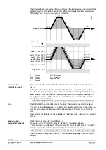
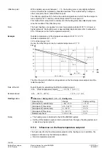
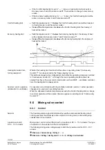
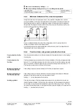
Due to the room temperature deviation
Δ
TV, the change of flow temperature setpoint
corresponds roughly to the value of:
Δ
TFl=
Δ
TR × V × (sHc + 1)
Δ
TFl Change of flow temperature setpoint
sHc Heating curve slope
Δ
TR Change of room temperature setpoint
Sp
Setpoint
V
Room temperature influence
TRx Room temperature
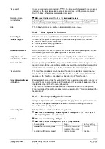
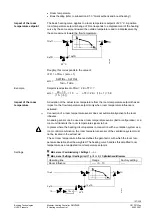
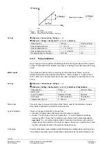
During boost heating, the room temperature setpoint increase also produces an in-
crease of the flow temperature setpoint. In that case, the greatest of the 2 values is
used for generating the setpoint.
31
31
B
22
SpTR
TR
+
-
TR
TR × V
-
TRBoost
MAX
TReff
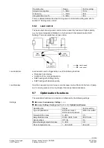
The resulting room temperature setpoint has a minimum limitation of 5 °C and a maxi-
mum limitation of 35 °C.
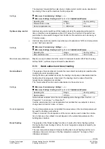
Only one solar intensity sensor can be connected to a controller. For configuration and
parameterization, refer to chapter 12 “Function block miscellaneous”.
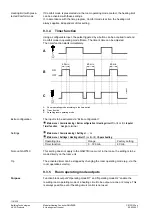
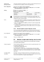
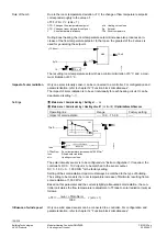
The impact of solar radiation is to be set individually for each heating circuit. It can be
deactivated (setting ”---“).
Main menu > Commissioning > Settings > …
or
Main menu > Commissioning > Heating circuit 1
(or
2
or
3
)
> Optimizations/influences
Operating line
Range
Factory setting
Impact of solar radiation
---- / 0.0…15.0 K
----
31
31
B
23
TOeff
Isun
SpTFlDe
SpTFlHi
SpTRN
TFl
TOeff
TODe
TOHi
sHc
-
+
TFl
sHc
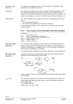
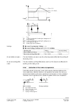
TFl =
Isun × TRsnNom
1000 W/m
2
× (sHc + 1)
Δ
TRsnNom Room temperature increase with 1000 W/m
2
Isun Filtered
solar
radiation
sHc
Heating curve slope
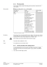
The solar intensity sensor is to be configured via “Extra configuration”. If required, the
controller’s DC 0…10 V input is to be matched to the sensor output.
DC 0…10 V
≅
0…1,000 W/m
2
is the factory setting.
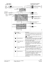
Setting of the solar radiation impact must always be matched to the type of building.
The setting to be made is the room temperature increase
Δ
TRsnNorm resulting from a
solar radiation of 1,000 W/m
2
.
Based on this parameter and the current (slightly) attenuated solar radiation, the con-
troller calculates the flow temperature readjustment
Δ
TFl due to solar radiation (Isun) as
follows:
Isun ×
Δ
TRsnNorm
Δ
TFl =
1000
× (sHc + 1)
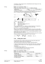
Only one wind speed sensor can be connected to a controller. For configuration and
parameterization, refer to chapter 12 “Function block miscellaneous”.
Rule of thumb
Impact of solar radiation
Settings
Influence of wind speed


