227/238
Building Technologies
Modular Heating Controller RMH760B
CE1P3133en
HVAC Products
16 Appendix
05.02.2007
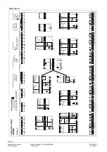
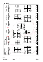
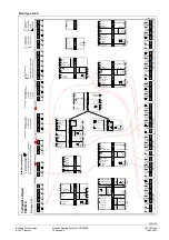
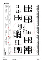
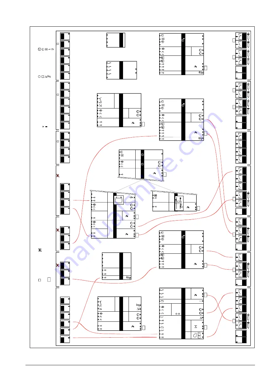
Plant type H4-5
a
a
a
ad
d
a
xx
1
2
xx
3
4
0...1
0 V
Y
Q
d
d
B
d
B
V
Q
2)
1)
3P
R1
Q
R2
Q
d
d
d
Q
YQ
a
a
a
a
d
d
a
Q
0...1
0 V
Y
Q
d
d
B
d
B
V
Q
2)
1)
3P
a
R1
Q
R2
Q
d
d
Q
a
a
a
a
d
d
a
Q
0...1
0 V
Y
Q
d
d
B
d
B
V
Q
2)
1)
3P
a
R1
Q
R2
Q
d
d
Q
RM
H7
60
N.
X5
x
N.
X
6
x
N.
X4
x
N.
X3
x
N.
X2
x
N.
X1
x
A7
.X
3
x
A7
.X
4
x
A7
.X
2
x
A7
.X
1
x
RM
Z7
89
(2
)
A9
.X
6
x
A9
.X
5
x
A9
.X3
x
A9
.X
4
x
A9
.X
2
x
A9
.X
1
x
RM
Z7
89
(1
)
(
)
A2
.X3
x
A2
.X
2
x
A2
.X
1
x
A2
.X
3
x
A2
.X
2
x
A2
.X
1
x
A3
.X3
x
A3
.X4
x
A3
.X
2
x
A3
.X
1
x
RM
Z7
82
(2
)
RM
Z7
83
RM
Z7
87
A9
.X
6
x
A9
.X
5
x
A9
.X3
x
A9
.X4
x
A9
.X
2
x
A9
.X
1
x
a
dd
d
Q
d
d
B
d
B
V
Q
1)
DC 0...
10
V
a
0...1
0 V
Y
a
2)
3P
a
d
d
d
Q
d
d
B
d
B
V
Q
1)
DC
0...10 V
a
0...1
0 V
Y
a
2)
3P
ii
ii
1
2
3
4
1.
2.
d
a
d
a
d
d
d
Q
d
Q
d
B
d
B
V
Q
a
0...1
0 V
Y
0...
10 V
Y
2)
2)
1)
3P
3P
Y
d
d
d
a
x
x
x
x
a
Q
a
a
d
0...1
0 V
Y
2)
3P
N.
Y1
Y
N.
Q
4
Q
N.
Q
1
Q
N.
Q
2
Q
N.
Q
3
Q
N.
Q
5
Q
A9
.Q2
Q
A9
.Q
3
Q
A9
.Q
4
Q
A9
.Q
1
Q
A7
.Q
1
Q
A7
.Q
2
Q
A7
.Q
3
Q
Q
A7
.Q
5
N1
N2
N1
N2
N3
N4
N.
Y2
Y
A9
.Y
1
Y
A9
.Y
2
Y
A9
.Q
2
Q
A9
.Q
3
Q
A9
.Q
4
Q
A9
.Q1
Q
N1
N2
N3
N4
A9
.Y
1
Y
A9
.Y
2
Y
3
P
3P
3P
3P
3P
A2
.Q
2
Q
A2
.Q
3
Q
N1
N2
A2
.Y
1
Y
3
P
A2
.Q
2
Q
A2
.Q
3
Q
N1
N2
A2
.Y
1
Y
3P
A3
.Q2
Q
A3
.Q
3
Q
A3
.Q
5
Q
N1
N2
A3
.Y
1
Y
3P
A3
.Q
4
Q
3
P
RM
Z7
82
(1
)
V
a
a
a
d
aa
d
d
d
Q
Y
3P
Y
3P
V
d
d
B
d
0...1
0 V
2)
B
0...
10 V
2)
1)
B
1)
B
V
d
d
d
B
d
a
Q
Q
B
0...1
0 V
Y
2)
3P
Q
d
d
1)
a
A2
.Q
1
Q
A2
.Q
1
Q
A3
.Q
1
Q
.
Flow
Retu
rn
Room
Room
rel
.
Timer
Roo
m abs.
Ope
rat
ing m
ode
close
open
Rela
y 1
Rela
y 2
He
a
ti
n
g
c
ir
c
ui
t
1
HC
-
pu
m
p
Faul
t b
utto
n
Hea
tin
g li
mit
Heat
ing
H
eat
de
m
and
Ope
rat
ing m
ode
Outs
ide
Flow
Retu
rn
Room
Room
rel
.
Roo
m abs.
Ope
rat
ing m
ode
Timer
open
close
HC
-
pu
m
p
Hea
tin
g li
mit
Oper
atin
g m
ode
Flow
Retu
rn
Room
Room
rel
.
Room
abs
.
Outs
ide
Ope
rat
ing m
ode
Timer
close
open
Heat
ing l
im
it
Oper
atin
g m
ode
HC
-
pu
m
p
He
a
ti
n
g
c
ir
c
ui
t 3
He
a
ti
n
g
c
ir
c
ui
t 2
X =
U
niv
er
sal
in
put
Y =
A
na
log
ou
tpu
t
Q
=
R
el
ay
o
ut
put
x =
A
na
log or
dig
ital
a =
A
nalog
d =
D
igi
tal
i =
P
ul
se
=
= C
ont
in
. out
put
= F
au
lt
= Fee
dba
ck
= T
ime
sw
itch
= Ho
liday
= S
pec
ia
l d
ay
= 2-
Po
s.
ou
tp
ut
To d
o
a
co
nf
igur
at
ion
Fr
om
c
ap
ital let
ter
to c
ap
ita
l let
ter
Fr
om
s
m
al
l let
te
r t
o
sm
all
le
tter
Cap
ital
let
ter
=
P
hy
sic
al
in-
or
out
put
Sm
all
let
ter
=
int
er
nal
s
ignal
= O
r-s
ele
ct
ion
= A
nd
-se
le
ct
io
n
H
eat
re
qu
is.
Fros
t
Flow
Re
tu
rn
close
open
Mai
n
pu
m
p
Disp
lay
1
Disp
lay
2
Di
spl
ay 3
Disp
lay
4
Wind
Sola
r
Outs
ide
Legi
one
lla
func
tion
rel
ay
Pr
im
ar
y
Flow
Retu
rn
Flow
Se
co
nd
ar
y
Co
n-
su
m
er
Ci
rc
u-
la
tion
Ta
nk
Ope
rat
ing m
ode
close
open
close
open
close
open
M
ain
ta
in
.
te
m
p.
Flu
e g
as
Rel
eas
e
Flu
e g
as m
ode
.
Bu
rn
er
Boile
r
Re
tur
n
Bu
rn
er
Shuto
ff v
alv
e
Boi
ler
p.
By
pa
ss
p.
(W
ater
shortage
) 1
(Ove
rpre
ssu
re) 2
(U
nder
pres
sure)
3
Pump f
unc
t:
B
o
ile
r
Mod
ul
at
ing
St
ag
e
close
open
Setp
oin
t com
p.
close
open
MB
RT
Flow
Re
tu
rn
Heat
ing
Fros
t
P
ri
m
ar
y
c
o
n
tr
o
ll
er
He
at
re
qu
is.
Sy
st
em
pu
m
p
close
open
top
bottom
Flow
Forc
ed c
har
ging
4
Ex
ten
sion m
odu
les
1)
6
Si
ng
le or
tw
in pum
ps
2)
6
C
on
tro
l o
ut
put
s (
D
C
0
...
10
V
or
3-
pos
iti
onin
g)
3-
Pos
iti
onin
g out
put
in
pa
irs
Q
1/
Q
2,
Q
3/
Q
4
C
onf
iguratio
n Diag
ra
m
RM
H7
60
B
M
axi
m
um
con
fig
ur
ati
on
:
Pl
an
t t
yp
e
M
isce
ll
an
eo
u
s
M
a
in
c
o
n
tr
o
lle
r
Faul
ts
Cou
n
te
r
DHW
Pr
im
ar
y
Retu
rn
Flow
sig
nal
Flow
close
open
Se
co
nd
ar
y
= f
ro
m
= t
o
3133W06_H4-5_en
H4
-5


