167/232
Building Technologies
Boiler sequence controller RMK770
CE1P3132en
HVAC Products
10 Heating circuit control
23.04.2009
31
31
B
20
TOeff
+
-
SpTR
TR
20 °C
SpTFlDe
SpTFlHi
SpTRN
TFl
TOeff
TODe
TOHi
+
-
+
-
+
+
TFl
SpTR
TR × V
-
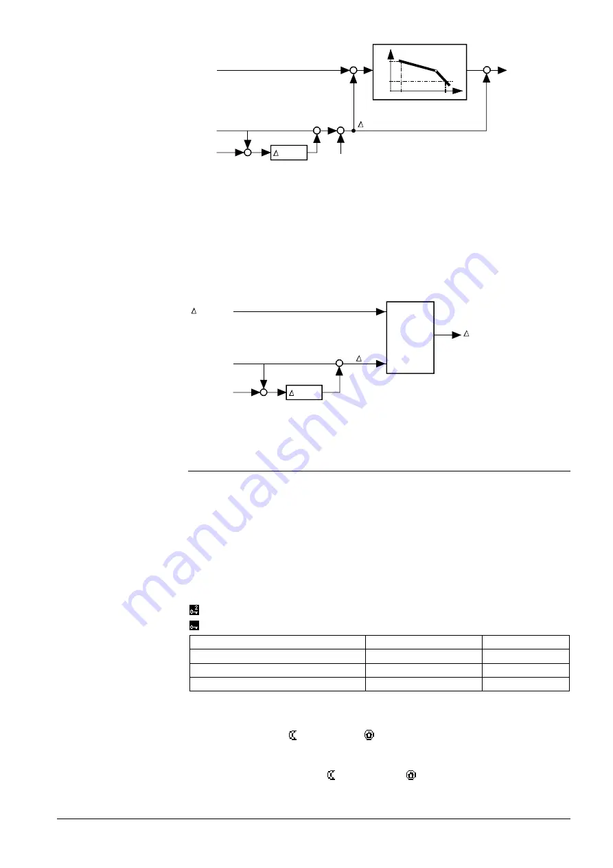
Due to the room temperature deviation
Δ
TV, the change of flow temperature setpoint
corresponds roughly to the value of:
Δ
TFl=
Δ
TR × V × (sHc + 1)
Δ
TFl Flow temperature setpoint change
sHc Heating curve slope
Δ
TR Room temperature setpoint change
Sp
Setpoint
V
Room influence
TRx Room temperature
During boost heating, the room temperature setpoint boost also produces an increase
of the flow temperature setpoint. In that case, the greatest of the 2 values is used for
generating the setpoint.
31
31
B
22
SpTR
TR
+
-
TR
TR × V
-
TRBoost
MAX
TReff
The resultant room temperature setpoint has a minimum limitation at 5 °C and a maxi-
mum limitation at 35 °C.
10.5.4 Heating limit switch
The heating limit switch can restrict the amount of heat delivered to the heating circuit.
This prevents the waste of heating energy at higher outside temperatures.
To determine the heating limit, the following outside temperature values are taken into
consideration (refer to subsection 10.5.1 “The composite and the attenuated outside
temperature”):
•
The current outside temperature TO
•
The composite outside temperature Toeff
•
The attenuated outside temperature TostrDmp
Main menu > Commissioning > Settings > …
or
Main menu > Settings > Heating circuit > Space heating
Operating line
Range
Factory setting
Comfort heating limit
---- / –5…25 °C
17 °C
Economy heating limit
---- / –5…25 °C
5 °C
Heat limit with Comfort preset
Inactive / Active
Inactive
Note the following:
•
When the Comfort heating limit is set to “----“ (no heating limit), a heating limit only
applies to Economy and Protection mode. And there is no changeover to sum-
mer operation
•
When the Economy heating limit is set to “----“ (no heating limit), the Comfort heating
limit takes effect in Economy
and Protection
mode
Rule of thumb
Settings


