background image

186/232 

Building Technologies 

Boiler Sequence Controller RMK770 

CE1P3132en 

HVAC Products 

11 Data acquisition 

23.04.2009 

11.2 Fault 

handling 


If a trend signal at the local inputs is no longer available (e.g. due to a faulty sensor), 
trends are no longer recorded. 
In this case, observe the fault status messages under: 


Main menu > Faults > Faults current 


If the values are not available via bus, trends are no longer recorded. 

 
After a power failure or when quitting the 

Extra configuration

 menu (restart controller), the 

values of the 8-hour and 8-minute views are deleted. 
However, the values of the 24-hour view and those of the last 6 days are retained.  

11.3 Meters 


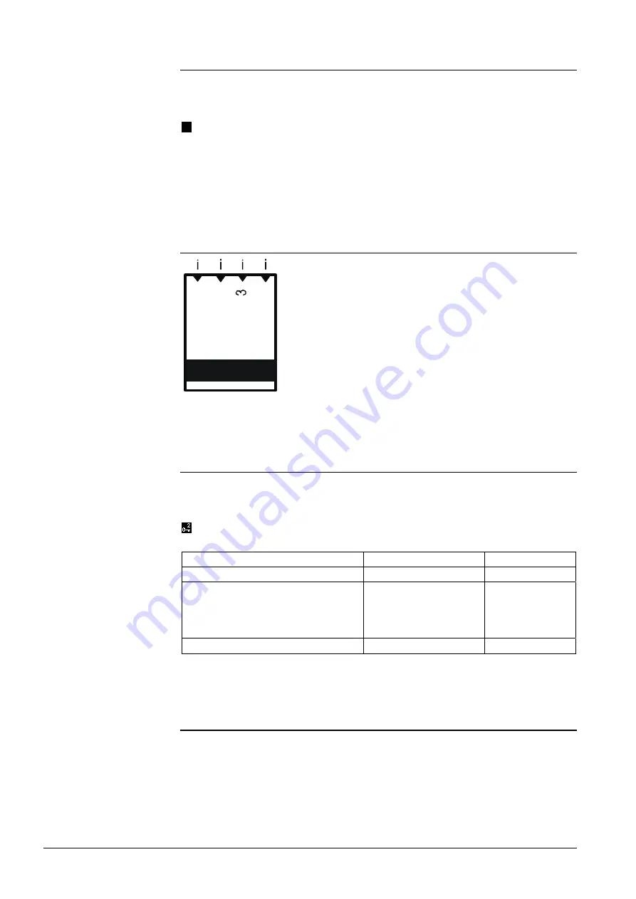
 1

 2

 4

Meter


i 1 

Meter input 1 

i 2 

Meter input 2 

i 3 

Meter input 3 

i 4 

Meter input 4 

11.3.1 Configuration 


Extra configuration 
The meters are activated in the extra configuration by assigning a terminal to the 
meter’s input. 


Main menu > Commissioning > Extra configuration > Data acquisition > Meter 1

 (or 

2

3

 or 

4


Operating line 

Range 

Factory setting 

Input 1 (etc. up to input 4)  

--- / RMK770.X1, etc. 

--- 

Displayed unit 

Wh / kWh / MWh / kJ / 
MJ / GJ / ml / l / m3 /  
Heat cost unit /  
No unit / BTU 

kWh 

Displayed format 

0 / 0.0 / 0.00 / 0.000 

 
Datapoint "Displayed unit" is used to select the unit to be displayed. Datapoint "Dis-
played format" defines the number of decimal places.  

11.3.2  Meter types  


Meters are used to acquire consumption values.  
Pulses from the following types of meter can be handled:  

  Gas meters  

  DHW meters  

  Drinking water meters  

 Electricity meters 


Trend signal not available 

Power failure or restart 

Settings  

Displays 

Summary of Contents for Synco RMK770

Page 1: ...tion 2 1 Controller series B CE1P3132en 23 04 2009 Building Technologies Synco 700 Modular boiler sequence controller RMK770 including extension modules RMZ785 RMZ787 RMZ788 and RMZ789 Basic Documentation ...

Page 2: ...C Products 23 04 2009 Siemens Switzerland Ltd Industry Sector Building Technologies Division International Headquarters HVAC Products Gubelstrasse 22 CH 6301 Zug Tel 41 41 724 24 24 Fax 41 41 724 35 22 www sbt siemens com 2004 2009 Siemens Switzerland Ltd Subject to alteration ...

Page 3: ...l assignment and properties of outputs 31 3 3 3 Short designations for basic module and extension modules 32 3 3 4 Maximum configuration 32 3 3 5 Use of configuration diagrams 32 3 3 6 Extension modules 34 3 4 Extra configuration 36 3 4 1 Hydraulics dependent inputs and outputs of function block Boiler sequence manager 37 3 4 2 Hydraulics dependent inputs and outputs of function block Boiler 38 3 ...

Page 4: ...t inputs 55 4 5 4 Electronic business card 55 4 5 5 Resetting text entries 56 5 General functions fundamentals 57 5 1 Time switch 57 5 1 1 Communication 57 5 1 2 Entering the 24 hour program for space heating 58 5 1 3 Fault handling 59 5 2 Holidays special days 59 5 2 1 Communication 59 5 2 2 Holidays 60 5 2 3 Special days 60 5 2 4 Calendar entry 61 5 2 5 Control inputs for holidays and special da...

Page 5: ...quest 2 position 92 6 5 3 Heat demand transformers 93 6 6 Other functions 93 6 6 1 Common maintained boiler return temperature 93 6 6 2 Maximum limitation of the flow temperature setpoint 94 6 6 3 Frost protection 95 6 7 Diagnostics 95 6 8 Fault handling 97 7 Boiler control 99 7 1 Overview of function block 99 7 2 Configuration 101 7 2 1 Burner types 103 7 2 2 Boiler hydraulics 104 7 3 Additional ...

Page 6: ...13 Boiler faults 124 7 14 Burner hours run counter and output balance 126 7 15 Fault status messages 127 7 16 Boiler designations 132 7 17 Diagnostic choices 132 8 Heat demand and heat requests 134 8 1 Heat requests 134 8 2 Weather compensated setpoint for boiler sequencing 135 8 3 Heat demand transformers 135 9 Precontrol 138 9 1 Overview of function block 138 9 2 Configuration 138 9 3 Types of p...

Page 7: ...g circuit 157 10 4 Room temperature setpoints 159 10 4 1 Settings 159 10 4 2 Increasing the Economy setpoint 160 10 4 3 Room temperature setpoint adjuster absolute 160 10 4 4 Room temperature setpoint adjuster relative 162 10 5 Weather compensated heating circuit control 162 10 5 1 The composite and the attenuated outside temperature 163 10 5 2 Heating curve 164 10 5 3 Influence on the flow temper...

Page 8: ... Configuration 186 11 3 2 Meter types 186 11 3 3 Pulse valency 187 11 3 4 Overflow value 188 11 3 5 Setting and resetting meter readings 188 11 3 6 Meter readings 188 11 3 7 Assignment of texts 189 11 3 8 Fault handling 189 12 Function block Miscellaneous 190 12 1 Overview of function block 190 12 2 Configuration 190 12 3 Outside sensor 190 12 3 1 Outside temperature simulation 192 12 3 2 Fault ha...

Page 9: ...a holidays and special days 207 14 3 Room data 208 14 3 1 Communication variants 208 14 3 2 Settings 208 14 3 3 Settings on the room unit 209 14 4 Heat generation zone and boiler sequence zone 209 14 5 Heat distribution zones 210 14 5 1 Heat demand and load control 211 14 5 2 Outside temperature 211 14 6 Fault handling 211 15 Fault tracing support 214 15 1 Fault code list 214 15 2 Rectification of...

Page 10: ...10 232 Building Technologies Boiler Sequence Controller RMK770 CE1P3132en HVAC Products Contents 23 04 2009 16 2 6 Meters 223 16 2 7 Devices 223 16 2 8 Menu tree 223 16 3 Info pages 224 ...

Page 11: ...785 Universal module with 4 inputs and 4 relay outputs RMZ787 Universal module with 4 inputs 2 analog outputs and 2 relay outputs RMZ788 Universal module with 6 inputs 2 analog outputs and 4 relay outputs RMZ789 Module connector For detached extension modules RMZ780 Operator units Operator unit plug in type RMZ790 Operator unit detached RMZ791 KNX bus operator unit RMZ792 Service unit Service tool...

Page 12: ...000 or T1 PTC N1721 N1846 N1713 Active sensors Sensors operating on AC 24 V with modulating DC 0 10 V output N1821 N1850 N1932 Monitors RAK QBM81 QVE1900 QVE1901 N1186 N1190 N1552 N1592 N1594 Room units QAA25 QAA27 QAW740 N1721 N1633 Passive setpoint adjusters QAA25 QAA27 BSG21 N1721 N1991 Active signal sources BSG61 N1992 Actuating devices Electromotoric and electrohydraulic actuators operating o...

Page 13: ...lation Instructions for RMH760B and RMK770 G3133 Mounting Instructions for extension modules RMZ78 M3110 Mounting Instructions for detached operator unit RMZ791 M3112 Mounting Instructions for module connector RMZ780 M3138 Operating Instructions for RMH760B 1 and RMK770 1 de fr it es B3133x1 Operating Instructions for RMH760B 2 and RMK770 2 en de fr nl B3133x2 Operating Instructions for RMH760B 3 ...

Page 14: ... to potential risks When wiring the system the AC 230 V section must be strictly segregated from the AC 24 V safety extra low voltage SELV section in order to ensure protection against electric shock hazard For storage and transport the limits given in the relevant Data Sheets must always be observed If in doubt contact your supplier or Siemens Building Technologies Synco 700 products are maintena...

Page 15: ...t use faulty peripheral devices 2 Button with LED red for indicating fault status messages and their acknowl edgement LED blinks Fault status message ready for acknowledgement LED lit Fault status message still present but not yet reset LED off No fault status message present Press button Acknowledge or reset fault 3 Program button Prog Learning button for switching between normal mode and address...

Page 16: ...leartext The controller is supplied with several languages programmed when commissioning the plant the required language must be activated The Operating Instructions for the enduser are included with the controller they contain the languages with which the controller is supplied 3 4 2 1 5 3111Z05 Plug in type operator unit RMZ790 3 4 3112Z08 2 1 5 Detached operator unit RMZ791 1 Display 2 INFO but...

Page 17: ... the corner at bottom right only access levels Service level and Password Main me Heating Heating Curvepoint 1 flow temp 486 Info level Display of key plant data Room operating mode Preselection State Comf Cause Time switch 2 2 3 Operating levels There are 2 operating levels The Info level The setting level These 2 levels are always active independent of the access level currently used When on thi...

Page 18: ...word and confirm by pressing the OK knob District heat parameters Press OK knob and ESC button simultane ously Then select parameter Password level and confirm by pressing the OK knob Enter number 11 for the password and confirm by pressing the OK knob Individual menu items or datapoints are enabled depending on the access level On a higher access level it is always possible to also display all me...

Page 19: ...ined with the plant type are assigned to boiler 1 and boiler 2 They are also given boiler addresses 1 and 2 on the KNX bus Further by selecting the plant type the common main flow and main return temperature sensors are predefined If additional boilers need to be configured this is to be made via the Extra configuration menu For additional boilers each plant element burner stages boiler sensor etc...

Page 20: ...e third boiler 2 choices are available Since the RMK770 controller does not have a sufficient number of outputs an exten sion module is required Now in the extra configuration boiler 3 is assigned the boiler temperature sensor the first burner stage the boiler pump and the shutoff valve T T T T 3132S43 CE Q11 D1 X8 Q24 Q23 G0 M M Y1 G1 G G1 X6 M X5 M M M X3 X2 M X4 M Q33 Q34 Q41 Q44 Q53 Q54 Q63 Q6...

Page 21: ...CE X1 G1 Q12 Q42 Q73 Q74 Y2 G0 X7 D2 M M G1 G0 G1 RMK770 2 Also on the first RMK770 the Number of boilers must be set to 3 thus informing the boiler sequence manager that a third boiler must be controlled via bus Main menu Commissioning Settings or Main menu Settings Boiler sequence manager Operating line Range Factory setting Number of boilers 1 6 2 T T T T 3132S45 CE Q11 D1 X8 Q24 Q23 G0 M M Y1 ...

Page 22: ...justable values remarks Plant type Basic type K K1 1 K6 3 Position 1 RMZ785 RMZ787 RMZ788 RMZ789 Position 2 RMZ785 RMZ787 RMZ788 RMZ789 Position 3 RMZ785 RMZ787 RMZ788 RMZ789 Operating line Plant type is used to enter or display the type of plant On lines Position 1 through Position 3 it is selected or displayed which of the exten sion modules is required If an extension module is provided for use...

Page 23: ... control of a modulating burner the 1 stage burner is used as the basic stage In addition a DC 0 10 V output must be assigned in the extra configu ration The plant type always applies to a boiler sequence with 2 boilers and using the same type of burner Additional boilers other types of burner a heating circuit or a primary controller can be configured in the extra configuration The plant type act...

Page 24: ...24 232 Building Technologies Boiler Sequence Controller RMK770 CE1P3132en HVAC Products 3 Commissioning 23 04 2009 K4 x 3132S10 K5 x 3132S13 M M K6 x 3132S16 ...

Page 25: ... burner 9 9 K6 3 Modulating burner 3 position 9 9 9 With the plant types the main flow and main return temperature sensors as well as the boiler temperature sensor are always preconfigured With plant type K6 x the boiler return temperature sensors are also preconfigured A main flow temperature is mandatory with all types of application If there is no main flow sensor the measured value can be adop...

Page 26: ... Boiler 1 boiler temperature sensor Bo1 TRtBo Boiler 1 boiler return temperature sensor Bo2 TBo Boiler 2 boiler temperature sensor Bo2 TRtBo Boiler 2 boiler return temperature sensor Bo1 BoPu Boiler 1 boiler pump Bo1 BuSt1 Boiler 1 burner stage 1 Bo1 BuSt2 Boiler 1 burner stage 2 Bo1 BuMdltUp Boiler 1 modulating burner on Bo1 BuMdltDn Boiler 1 modulating burner off Bo1 VlvRTMxUp Boiler 1 return mi...

Page 27: ...terminals K1 1 K1 2 K1 3 K2 1 K2 2 K2 3 RMK770 X1 TMnFl TMnFl TMnFl TMnFl TMnFl TMnFl RMK770 X2 TMnRt TMnRt TMnRt TMnRt TMnRt TMnRt RMK770 X3 Bo1 TBo Bo1 TBo Bo1 TBo Bo1 TBo Bo1 TBo Bo1 TBo RMK770 X4 RMK770 X5 RMK770 X6 Bo2 TBo Bo2 TBo Bo2 TBo Bo2 TBo Bo2 TBo Bo2 TBo RMK770 X7 RMK770 X8 RMK770 D1 RMK770 D2 RMK770 Y1 RMK770 Y2 RMK770 Q1 U Bo1 VlvShOf Bo1 VlvShOf Bo1 VlvShOf RMK770 Q2 Bo1 BuSt1 Bo1 ...

Page 28: ...770 RMZ789 RMK770 RMZ789 Plant type Connection terminals K3 1 K3 2 K3 3 K4 1 K4 2 K4 3 RMK770 X1 TMnFl TMnFl TMnFl TMnFl TMnFl TMnFl RMK770 X2 TMnRt TMnRt TMnRt TMnRt TMnRt TMnRt RMK770 X3 Bo1 TBo Bo1 TBo Bo1 TBo Bo1 TBo Bo1 TBo Bo1 TBo RMK770 X4 RMK770 X5 RMK770 X6 Bo2 TBo Bo2 TBo Bo2 Tbo Bo2 TBo Bo2 TBo Bo2 TBo RMK770 X7 RMK770 X8 RMK770 D1 RMK770 D2 RMK770 Y1 RMK770 Y2 RMK770 Q1 U Bo1 VlvShOf B...

Page 29: ...Q 14 C E X 1 G 1 Q 12 Q 42 Q 73 Q 74 Y 2 G 0 X 7 D 2 M M G 1 G 0 G 1 Y 1 4 G 0 Y 9 G 1 Y 1 3 B 1 X 2 X 3 M M M Y 2 3 Q 13 N 1 Y 2 4 Q 14 RMK770 RMZ789 RMK770 1 RMZ789 Connection terminals Plant type K5 1 K5 2 K5 3 RMK770 X1 TMnFl TMnFl TMnFl RMK770 X2 TMnRt TMnRt TMnRt RMK770 X3 Bo1 TBo Bo1 TBo Bo1 TBo RMK770 X4 RMK770 X5 RMK770 X6 Bo2 TBo Bo2 TBo Bo2 TBo RMK770 X7 RMK770 X8 RMK770 D1 RMK770 D2 RM...

Page 30: ...4 RMZ789 RMK770 2 RMZ789 Connection terminals Plant types K6 1 K6 2 K6 3 RMK770 X1 TMnFl TMnFl TMnFl RMK770 X2 TMnRt TMnRt TMnRt RMK770 X3 Bo1 TBo Bo1 TBo Bo1 TBo RMK770 X4 Bo1 TRtBo Bo1 TRtBo Bo1 TRtBo RMK770 X5 RMK770 X6 Bo2 TBo Bo2 TBo Bo2 TBo RMK770 X7 Bo2 TRtBo Bo2 TRtBo Bo2 TRtBo RMK770 X8 RMK770 D1 RMK770 D2 RMK770 Y1 RMK770 Y2 RMK770 Q1 U Bo1 BoPu Bo1 BoPu Bo1 BoPu RMK770 Q2 Bo1 BuSt1 Bo1 ...

Page 31: ...mixing valve or modulating burner with on off signal appropriate radio interference suppression measures must be taken If the mixing valve does not already incorporate such RC units appropriate devices must be provided either on the controller side or externally With the RMZ789 extension module there are 4 mixing valve outputs available where an RC unit can be easily activated Q11 Q14 Q12 C R Q24 ...

Page 32: ...9 These short designations also appear o the display of the operator unit 3 3 4 Maximum configuration The configuration diagram in the Addendum gives an overview of the maximum number of function blocks that can be configured Quantity Type of function block 1 Boiler sequence manager 6 Boiler 7 Output modulating 3 position or DC 0 10 V 7 Pump block for single or twin pumps 1 Miscellaneous 1 Primary...

Page 33: ...line Position 1 If required the output for the first or the second boiler pump can also be configured to some other output It is also possible to change the type of extension module On function block Boiler sequence manager the main flow temperature sensor N X1 and the main return temperature sensor N X2 are preconfigured This can be checked on Extra configuration Boiler sequence manager Inputs On...

Page 34: ... close Heating circuit DC 0 10 V Flow Heating curve close Primary controller DHW Display 1 Display 2 Display 4 Miscellaneous Relay 1 Relay 2 Faults Fault button More detailed information about these function blocks is provided in the following subsections 3 3 6 Extension modules RMK770 RMZ78 RMZ78 RMZ78 3132Z08 A maximum of 3 extension modules per RMK770 can be used Prior to attaching an extension...

Page 35: ...ontrol of 3 position actuators with RC units can be activated The extensions can be activated by configuring them at a free position of the controller Position 1 Position 2 RMK770 RMZ788 RMZ787 The settings are to be made as follows Main menu Commissioning Basic configuration Operating line Adjustable values remarks Plant type Basic types K K1 1 K6 3 Position 1 RMZ788 Position 2 RMZ787 At position...

Page 36: ...valves etc In most cases the configured outputs determine the plant s hydraulic circuit Additional inputs and outputs can activate various functions A description of these extra configurations is given with the relevant function block Main menu Commissioning Extra configuration Boiler 1 Inputs Operating line Range Factory setting Flue gas temperature sensor RMK770 RMZ7 Here the free outputs are av...

Page 37: ...ump RMK770 RMZ7 MnPu_A Main pump B MnPu_B Maint boiler return temp 3 pos MnVlvRtMx Maint boiler return temp mod MnVlvRtMx Here the free inputs are available for selection The main flow temperature is the main controlled variable of the boiler sequence and must always be available with the boiler master for more detailed information refer to section 3 5 Several boiler sequence controllers RMK770 If...

Page 38: ... PrCtrVlvMx TRtPrCtr TFlPrCtr TPu_A TFg T TPu_B BoPu_A VlvRtMx T TRtBo BuSt1 BuSt2 TBo T TFg T _B T MnPu_A MnPu_B Main menu Commissioning Extra configuration Boiler Inputs Operating line Range Name Boiler sensor RMK770 RMZ7 TBo Return sensor TrtBo Flue gas temperature sensor TFg Here the free inputs are available for selection This sensor is automatically configured when selecting a plant type exc...

Page 39: ...Boiler pump or bypass pump Boiler pump B if the boiler pump is a twin pump Shutoff valve 3 position or modulating mixing valve for maintained boiler return temperature for restriction with 3 position output refer to subsection 3 3 2 Terminal assignment and properties of outputs For more detailed information refer to chapter 7 Boiler control 3 4 3 Hydraulics dependent inputs and outputs of function...

Page 40: ...rol For more detailed information refer to chapter 9 Precontrol 3 4 4 Hydraulics dependent inputs and outputs of function block Heating circuit T T TRtCo TRtMn T TMnFl T T T PrCtrVlvMx TRtPrCtr TFlPrCtr TPu_A T T T TRtHCtr TFlHCtr HCtrPu_A T T T TFlHCtr HCtrVlvMx TRtHCtr HCtrVlvMx HCtrPu_A Tr TPu_B HCtrPu_B HCtrPu_B T Main menu Commissioning Extra configuration Heating circuit Operating line Range...

Page 41: ... is created In that case setting Heating circuit active inactive is of no importance This setting defines whether the heating circuit is connected directly to the main header or downstream from the primary controller Flow temperature sensor Room temperature sensor Return temperature sensor Digital input for activating the Special day function Digital input for activating the Holidays function Heat...

Page 42: ...ng Extra configuration Miscellaneous Business card Operating line Range Factory setting Business card No Yes Yes For more detailed information refer to chapter 12 Function block Miscellaneous 3 4 6 Faults Main menu Commissioning Extra configuration Faults Inputs Operating line Range Factory setting Fault button external RMK770 RMZ7 Fault input 1 Fault input 2 Fault input 3 Fault input 4 Here the f...

Page 43: ...a high limit value Main menu Commissioning Settings or Main menu Settings Inputs X Operating line Range Factory setting Value low Depending on the selected type Depending on the type Value high Depending on the selected type Depending on the type Flow temperature with an active signal of DC 0 10 V 0 100 C Low limit value 0 C High limit value 100 C With a passive temperature sensor the measured val...

Page 44: ...tiboiler plant must be assigned to several RMK770 controllers But there may also be other reasons to have the plant controlled by several RMK770 In that case one of the RMK770 controllers provides the boiler master function And function block Boiler sequence manager is activated only in that RMK770 This func tion block controls the boilers of the other RMK770 via bus The boiler master is defined b...

Page 45: ...ttings it is recommended to conduct this test At the inputs the current states or values are displayed The aggregates pumps actuators etc connected to the outputs can be switched In the case of modulating outputs a signal can be delivered in the relevant value range The application is deactivated during the wiring test The outputs are in a defined OFF state safety related functions are deactivated...

Page 46: ...ate after commissioning Main menu Data backup Operating line Remarks Storage date Display of the date on which the commis sioning data set was downloaded to the controller s memory Storage year Display of the year in which the commission ing date set was downloaded to the control ler s memory Main menu Data backup Operating line Remarks Restore Caution New configuration Save Caution Stored data wi...

Page 47: ...t the user level by turning the OK knob 5 Confirm selection by pressing the OK knob 3 11 Marking changes If the internal standard application has been adapted or if subsequently submenu Extra configuration has been accessed an asterisk is placed in front of the plant type s type reference The asterisk denotes that the basic type was complemented by extra functions The asterisk is set automatically...

Page 48: ...t terminal assignments The terminal markings used are explained at the end of this section K1 1 3132S19 N X3 N X6 N X1 N X2 N Q2 N Q5 N Q7 K1 2 3132S20 N X3 N X6 N X1 N X2 N Q2 N Q3 N Q5 N Q6 N Q7 1 2 1 2 K1 3 3132S21 N X3 N X6 N X1 N X2 N Q2 A9 Q1 A9 Q4 A9 Q2 N Q5 A9 Q3 N Q7 K2 1 3132S22 N X3 N X6 N X1 N X2 N Q2 N Q1 N Q4 N Q5 N Q7 M M Note ...

Page 49: ... Q5 N Q6 N Q7 1 2 1 2 M M K2 3 3132S24 N X3 N X6 N X1 N X2 N Q2 N Q1 N Q4 A9 Q1 A9 Q4 A9 Q2 N Q5 A9 Q3 N Q7 M M K3 1 3132S25 N X3 N X6 N X1 N X2 N Q3 N Q6 N Q2 N Q1 N Q4 N Q5 N Q7 M M K3 2 3132S26 N X3 N X6 N X1 N X2 A7 Q1 A7 Q2 N Q2 N Q1 N Q4 N Q3 N Q5 N Q6 N Q7 1 2 1 2 M M K3 3 3132S27 N X3 N X6 N X1 N X2 N Q3 N Q6 N Q2 N Q1 N Q4 A9 Q1 A9 Q4 A9 Q2 N Q5 A9 Q3 N Q7 M M ...

Page 50: ... X6 N X1 N X2 N Q1 N Q4 N Q2 N Q5 K4 2 3132S29 N X3 N X6 N X1 N X2 N Q1 N Q4 N Q2 N Q6 N Q3 N Q5 1 2 1 2 K4 3 3132S30 N X3 N X6 N X1 N X2 N Q1 N Q4 N Q2 A9 Q1 A9 Q4 A9 Q2 N Q5 A9 Q3 K5 1 3132S31 N X3 N X6 N X1 N X2 N Q3 N Q6 N Q1 N Q4 N Q2 N Q5 M M K5 2 3132S32 N X3 N X6 N X1 N X2 A7 Q1 A7 Q2 N Q1 N Q4 N Q2 N Q6 N Q3 N Q5 1 2 1 2 M M ...

Page 51: ...2 K6 3 3132S36 N X3 N X6 N X1 N X2 N X4 N X7 N Q1 N Q4 N Q2 A9 Q3 A9 Q4 A9 2 Q3 A9 2 Q4 A9 Q1 A9 2 Q2 A9 Q2 N Q5 A9 2 Q1 Explanation of the terminal markings used Boiler with 1 stage burner 1 2 Boiler with 2 stage burner Boiler with modulating burner 3 position N Connection terminal on the controller X1 Configurable input at the controller Q1 Relay with terminals Q11 Q12 and Q14 Q2 Relay with term...

Page 52: ...ates set for the change from wintertime to summertime or vice versa ensure that on the first Sunday after that date the time of day will change from 02 00 wintertime to 03 00 summertime and from 03 00 summertime to 02 00 wintertime If both dates are set to coincide summer wintertime changeover is inactive Main menu Time of day date Operating line Range Factory setting Summertime start 01 01 31 12 ...

Page 53: ... of day is continuously and automatically matched to the system time 3140Z06 Contr time System time Readjustment Master The time of day on the controller can be readjusted and at the same time adjusts the system time The controller s time of day is continuously and automatically matched to the system time Contr time System time Readjustment Only one clock time master per system may be used If seve...

Page 54: ...gs or Main menu Settings Device Operating line Range Factory setting Language English Available with all types 4 3 Selecting the unit of temperature On the RMK770 the unit of temperature can be switched between C K and F Main menu Commissioning Settings or Main menu Settings Device Operating line Range Factory setting Unit C F C 4 4 Contrast of the operator unit s display The contrast of the displ...

Page 55: ...for the universal fault inputs can be edited on Main menu Settings Faults the text for the aggregate related faults at the relevant aggregate e g Settings Boiler 1 Fault settings Main menu Commissioning Settings or Main menu Settings Faults Fault input 1 or 2 3 or 4 Operating line Range Factory setting Fault text Max 20 characters Fault input 1 Fault Fault text Max 20 characters Fault input 2 Faul...

Page 56: ...04 2009 4 5 5 Resetting text entries The following datapoints cannot be reset Device name File name Business card line 1 4 All the other texts entered by the user such as menu texts fault texts etc can be reset at the password level Main menu Settings Texts Operating line Range Factory setting Reset text No Yes ...

Page 57: ...aphical zone apartment Autonomous Time switch slave apartment Geographical zone apartment 1 126 Master Time switch slave apartment Geographical zone apartment Slave Time switch slave apartment 1 126 Following combinations are possible Entry Effect Diagram Autono mous Time switch only acts locally on this controller It has no impact on other controllers on the bus Slave The time switch of this cont...

Page 58: ...r an entry following must be entered Time of day from where the desired operating mode shall apply The required operating mode The next day always adopts the operating mode of the previous day until a specific entry is made Diagram The operating mode of the previous day is shown as a broken line Cmf PreCmf Eco 1 3131D25 Monday Tuesday Wednesday If no entry is made for a specific day the operating ...

Page 59: ...roller operates in Comfort mode and fault status message System time switch failure 1 is delivered 5 2 Holidays special days Days deviating from the normal 7 day program can be entered by the plant operator as holidays or special days using the Holidays special days menu Entry is described in the Operating Instructions B3133x For each RMK770 controller a holidays special day program is available T...

Page 60: ...s are periods of time during which the building is not occupied whose start and duration are known in advance Examples Works holidays in commercially used spaces and buildings School holidays in school buildings Public holidays The operating mode to be used during the holiday period can be individually selected for each heating circuit and each DHW heating facility For the heating circuits the fol...

Page 61: ...inputs for holidays and special days Holidays and special days can also be activated via digital inputs For that purpose digital inputs must be assigned Main menu Commissioning Extra configuration Heating circuits Inputs Operating line Range Factory setting Holiday input RMK770 RMZ7 Special day input RMK770 RMZ7 Here the free inputs are available for selection These inputs are active only if holid...

Page 62: ...he holidays special day program only the first 2 entries are considered If more than 2 overlapping entries are made it may be that the special day no longer has priority over the holidays 5 3 Frost protection for the plant Main menu Commissioning Settings or Main menu Settings Protective functions Operating line Range Factory setting Frost prot for plant ON cycling 5 10 C 2 C Frost prot for plant ...

Page 63: ...hut down To ensure that the heat con sumers still draw heat during a minimum period of time an overrun time is enforced on the heat consumers that were not switched off more than 1 minute ago During the overrun time the pumps and mixing valves continue to operate the pumps continue to run and the mixing valves maintain the former setpoint The duration of the overrun time is dependent upon the type...

Page 64: ...re used they are kicked one after the other After the end of a kick the next pump will be kicked after an interval of 30 seconds The valve kick does not act on the shutoff valves 5 6 Heat demand and load control 5 6 1 Heat demand Heat consumers like heating circuits and DHW heating send their heat demand signals to the heat distribution zone Heat generation An RMU universal controller or RXB indiv...

Page 65: ...here a load reduction can be triggered are the following Protective boiler startup the boiler temperature is still below the minimum boiler temperature Load reduction via critical locking signals Maintained boiler return temperature without separate mixing valve acting on the heating circuits Load reduction via critical and uncritical locking signals Shifting DHW priority if the boiler temperature...

Page 66: ...een 0 and 200 Setting Response 0 Locking signal is ignored 100 Locking signal is adopted 1 to 1 200 Locking signal is doubled This enables the heat consumer s responses to be matched to the locking signals If the heat consumer responds too strongly the value must be decreased if its re sponse is too weak the value must be increased Ventilation controller and individual room control do not respond ...

Page 67: ... a 3 port mixing valve In the case of difficult controlled systems e g heating circuit with heat exchanger the control parameters must always be matched to the controlled system T T A controlled system is usually characterized by the step response This is explained in the following example of a mixing heating circuit At the point in time to the actuating device actuator of mixing valve shall be op...

Page 68: ...ctual plant it is not always possible to get a reliable step response Without a step response or in the case of unsatisfactory control action after entry of the calculated parameters the on off pulses after a setpoint step give hints for setting the parameters A distinction is to be made between 2 cases A B 3131D12 Setpoint Open pulse Close pulse Open pulse Close pulse Flow temp A The control puls...

Page 69: ...ve travel as this would be the case with the P part For example an integral action time of 120 seconds means that in the event of a control deviation of 5 K in the above example Xp 40 K it takes the mixing valve 120 seconds to travel 2 12 5 toward the fully open or fully closed position 12 5 due to the P part and 12 5 due to the I part If the integral action time is increased the control system re...

Page 70: ... sequence manager Outputs Main menu Commissioning Extra configuration Boiler Outputs Main menu Commissioning Extra configuration Primary controller Outputs Main menu Commissioning Extra configuration Heating circuit Outputs Operating line Adjustable values remarks pump Assign terminal pump B Assign terminal When in addition to the pump pump B is configured a single pump becomes a twin pump For thi...

Page 71: ...vent of fault changeover to pump A takes place After rectification of the fault changeover back to pump B takes place The changeover time is the same time as that used for the pump mixing valve kick kick day and kick time For this reason this setting must be checked Automatic changeover takes place on completion of 168 hours 7 days or after a new plant start when the kick day and kick time are rea...

Page 72: ...mes faulty changeover to the other pump takes place In any case a fault status message is delivered For acknowledgements following applies A fault due to a missing fault status message must be acknowledged and reset With faults resulting from overload the acknowledgement and reset behavior can be parameterized If a pump becomes faulty the relevant function block is stopped With twin pumps the faul...

Page 73: ...r sequence management 6 1 Overview of function block Auto DC0 10 V Main flow Summer operation DHW Frost protection close Heating curve T T T TMnRt TMnFl MnVlvRtMx TRtMx T TRtCo P WLoLeDet MnPu_A MnPuEr_A MnPuErFlow PMaxMon V PMinMon 1 2 3 4 5 6 Auto T T T T BSS BS Release HD HD gen HD DC 0 10 V HD DHW HD Frost MnPu_B MnPuEr_B P 3132S57 ...

Page 74: ...lt input 3 minimum pressure sensor BSS1 Boiler sequence selection input 1 BSS2 Boiler sequence selection input 2 BSS3 Boiler sequence selection input 3 Release BS Release input Summer Summer operation input HD DC 0 10 V Heat request modulating HD gen Heating curve request 2 position HD DHW DHW request 2 position HD Frost Frost protection request 2 position 6 2 Configuration Function block Boiler s...

Page 75: ...supervision of main pump B with twin pumps Flow signal Digital input for flow supervision of main pump MBRT return sensor Sensor for maintained main return tempera ture Fault input 1 Digital input for fault supervision of boiler sequence Fault input 2 Digital input for fault supervision Fault input 3 Digital input for fault supervision Boil sequence selection input 1 Control input 1 for boiler seq...

Page 76: ...figured the main pump is automatically set as a twin pump The main pump always operates when there is demand for heat If sustained mode is required for the boiler sequence Settings Boiler sequence manager Sustained mode can be used to parameterize whether the main pump shall also operate in sustained mode For types of plant without individual maintained boiler return temperature a common maintaine...

Page 77: ...d by the main flow sensor from the setpoint The setpoint correction can be adjusted Main menu Commissioning Settings or Main menu Settings Boiler sequence manager Control parameters Operating line Range Factory setting Boiler setpoint boost max 0 100 K 10 K An increase can be applied to the boiler temperature setpoint of the lag boilers Main menu Commissioning Settings or Main menu Settings Boiler...

Page 78: ... 4 5 6 1 2 3 5 Boiler sequence 5 6 1 2 3 4 6 Boiler sequence 6 1 2 3 4 5 The boiler sequence can also be preselected with an external selector In that case the selection on the operator unit is deactivated 1 2 3 4 5 6 Auto Main menu Commissioning Extra configuration Boiler sequence manager Inputs Operating line Adjustable values remarks Boil sequence selection input 1 Assign terminal Boil sequence...

Page 79: ...depending on the burner hours run of the lead boiler The burner hours run are calculated by the boiler sequence manager and are inde pendent of the hours run counters of the individual boilers Automatic boiler changeover ensures that the number of burner operating hours of the individual boilers are pretty much the same Main menu Commissioning Settings or Main menu Settings Boiler sequence manager...

Page 80: ...tal requirements and which therefore may only be used to a limited extent If a boiler is defined as a backup boiler that boiler is always the last to be switched on Several boilers can be defined as backup boilers These are then switched on in as cending order Main menu Commissioning Settings or Main menu Settings Boiler Operation settings Operating line Range Factory setting Backup boiler Yes No ...

Page 81: ...Priority 2 is assigned to all the other boilers with no restriction Priority 3 is assigned to the backup boilers Priority 4 is assigned to the boilers with locking by the outside temperature Priority 5 is assigned to the boilers with conditional manual locking release input Priority 6 is assigned to the boilers with unconditional manual locking release input The boiler released first is always the...

Page 82: ...e certain that several boilers with their burner stages do not cycle simultaneously With a small setpoint increase or no increase at all the relevant lag boiler also pro vides control This can be especially desirable in the case of boiler sequences with several modulating burners Boiler sequence with 4 boilers and modulating burners as an example Lag boilers with small setpoint increase or no incr...

Page 83: ...300 320 340 360 380 400 0 20 40 60 80 100 120 140 160 180 200 220 240 260 280 300 320 340 360 380 400 3132D03 Heat demand or load Boiler 1 Boiler 2 Main menu Commissioning Settings or Main menu Settings Boiler sequence manager Control parameters Operating line Range Factory setting Boiler sequence strategy Sequentially Binary sequentially Sequentially 6 3 4 Boiler sequence operating mode or Main m...

Page 84: ... boiler sequence operating mode selection on the operator unit and the summer operation input The input s operating action can be parameterized Main menu Commissioning Settings or Main menu Settings Inputs RMK770 or RMZ78 Operating line Range Factory setting Normal position Open Closed Open Normal position Open means that when the contact is open the boiler sequence is not released or that boiler ...

Page 85: ...f the relevant boiler is maintained depending on the pa rameter setting made independent of the sustained mode setpoint Also it can be selected whether or not a main pump if installed shall run during sustained mode If released in sustained mode the main pump practically always runs Main menu Commissioning Settings or Main menu Settings Boiler sequence manager Sustained mode Operating line Range F...

Page 86: ...ng mode Main menu Commissioning Settings or Main menu Settings Boiler sequence manager Control parameters Operating line Range Factory setting Shortened upward sequence DHW 0 100 0 The percentage of the shorter upward sequence for DHW determines how much earlier the boiler shall be released For example if the value is at 25 performance of the integral for the second boiler is started after of the ...

Page 87: ...ng off via the output balance prevents a large number of boilers from operating at low output although heat demand could be covered by a smaller number of boilers Main menu Commissioning Settings or Main menu Settings Boiler sequence manager Control parameters Operating line Range Factory setting Downward sequence output limit 0 100 If several boilers maintain simultaneously the same setpoint e g ...

Page 88: ...es that is below 60 kW on average After switch ing off the operating point of the remaining 3 boilers is at 80 kW To enable the third boiler to be switched off all 3 boilers must have modulated below 180 kW 60 of 300 kW for the duration of the switch off delay that is below 60 kW on average After switching off the operating point of the remaining 2 boilers is at 90 kW To enable the second boiler t...

Page 89: ...ed and reset 2494 Main pump B no flow Nonurgent message must be acknowledged and reset 2495 Main pump fault Urgent message must not be acknowl edged plant stop For fault supervision of the boiler sequence there are 3 binary fault inputs available These are freely configurable whereby the 3 fault outputs use the following factory settings Main menu Commissioning Settings or Main menu Settings Boile...

Page 90: ...s In addition to the 3 binary fault inputs the temperature at the main flow sensor can be monitored If the main flow temperature does not reach the required level within the adjustable fault status signal delay a fault status message is delivered It is only moni tored whether the required temperature is reached If the temperature is too high no fault status message is delivered reason in the case ...

Page 91: ...demand and heat request MAX Heat request continuous DC 0 10 V Heat request heating circuits Heat request DHW heating Heat request precontrol heating ventilation individual room control Heat request DHW Heat request frost Setpoint preselection manual Setpoint sustained mode Heat curve request 2 position Function block Boiler sequence manager collects the heat requests from all consumers heating cir...

Page 92: ...C 0 10 V signal source Main menu Commissioning Settings or Main menu Settings Boiler sequence manager Heat request Operating line Range Factory setting Modulating setpoint at 0 V 150 50 C 0 C Modulating setpoint at 10 V 50 500 C 100 C Modulating limit value 0 140 C 10 C DC 0 10 V 0 2 4 6 8 10 20 0 20 40 60 80 100 120 C 2 3 3131D14 c Value in C at DC 0 V d Value in C at DC 10 V e Limit value for he...

Page 93: ...onstant setpoint can be preselected A heating curve request can be ignored in the summer while consideration is given to frost protection requests depending on the plant s state Whether the input shall be active with the contact open or closed can be parameterized for each input Main menu Commissioning Settings or Main menu Settings Inputs RMK770 X or RMZ78 Operating line Range Factory setting Nor...

Page 94: ...he amount of heat drawn by the consum ers For more detailed information refer to subsection 5 6 2 Load control The type of locking signals can be selected on submenu Limitations Main menu Commissioning Settings or Main menu Settings Boiler sequence manager Limitations Operating line Range Factory setting Lock sig maintained boil ret temp None Uncritical Critical Critical The main pump like the boi...

Page 95: ...rn temperature sensor TrtCo falls below 5 C a heat request of 10 C is generated If the temperature at the sensor returns to a level above 7 C the function is deactivated The function is active for a minimum of 5 minutes 6 7 Diagnostics The first diagnostic choice is offered by the info pages Boiler sequence Boiler se quence manager Temperatures and Boilers Info page Boiler sequence shows The numbe...

Page 96: ...perating line Range Number of avail boil 0 6 Address number lead boiler 1 6 Address number 1st lag boiler 1 6 Address number 2nd lag boiler 1 6 Address number 3rd lag boiler 1 6 Address number 4th lag boiler 1 6 Address number 5th lag boiler 1 6 Main menu Boiler sequence manager Temperatures boilers Operating line Range Boil address no 1 actual temp C Boil address no 2 actual temp C Boil address n...

Page 97: ...ing line Range MBRT return min Inactive Active Setpoint maximum limitation Inactive Active 6 8 Fault handling Number Text Effect 330 Main flow sensor error Urgent message must be acknowledged and reset plant stop 331 Main return sensor error Nonurgent message must be acknowl edged no plant stop Number Text Effect 2491 Main pump overload Nonurgent message acknowledgement can be parameterized factor...

Page 98: ... no plant stop Number Text Effect 5593 Number of boilers wrong setting Nonurgent message must not be ac knowledged 5594 Invalid lead boiler Nonurgent message must not be ac knowledged 2202 Main contr h request mod error Nonurgent message must not be ac knowledged no plant stop 5591 Failure boiler sequence manager Nonurgent message no plant stop must be acknowledged 5592 1 boiler sequence man ager ...

Page 99: ...verview of function block DC 0 10 V DC 0 10 V Shutoff valve Setpoint comp close close Shutoff valve ErBu PMinMon Er2 WLoLeDet Er1 BoPuEr_A BuFb TBo BoPuEr_B TRtBo TFg BoPu_A BoPu_B BuSt1 BuSt2 BuMdltUp BuMdltDn BuMdlt_0 10 V BoSetpt VlvShOff VlvRtMxUp VlvRtMxDn VlvRtMx_0 10 V PMaxMon Er2 BuMdltFb BoPuErFlow ShOffVlvFb 3132S61 T P V P T T ...

Page 100: ... modulating burner TFg Flue gas sensor InFgMs Flue gas measuring mode contact BoPuEr_A Boiler pump overload BoPuEr_B Boiler pump B overload BoPuErFlow Flow signal pump ShOffVlvFb Checkback signal shutoff valve Er1 WLoLeDet Fault input 1 water shortage Er2 PMaxMon Fault input 2 maximum pressure Er3 PMinMon Fault input 3 minimum pressure InIndOp Individual operation Outputs BuSt1 Burner stage 1 BuSt...

Page 101: ...aulics appropriate adaptations can be made in the extra configuration If with plant type K2 2 burner stage 2 is removed from the first boiler the 2 stage burner of the first boiler is converted to a 1 stage burner By assigning an output terminal to burner stage 2 in plant type K2 1 the 1 stage burner is converted to a 2 stage burner In the extra configuration it is also possible to activate additi...

Page 102: ...er is made possible with the checkback signal burner If the checkback signal is not received after an adjustable period of time the burner initiates lockout With the burner checkback signal the burner hours run counter is started only after the checkback signal has been received When there is no checkback signal the burner hours run counter is started with the output signal for stage 1 In this way...

Page 103: ... configuration First burner stage or basic stage of a modulating burner Second burner stage Configuration of a pair of terminals for a modulating 3 position burner Available for selection are the remaining free terminal pairs Q1 Q2 Q3 Q4 Q5 Q6 for the open and the close signal Normally special terminal pairs are required RC unit for radio interference suppression for more detailed information refe...

Page 104: ...ned an output The single pump or twin pump can be monitored with a fault input and or a flow switch For more detailed information refer to section 5 8 Pump control If in addition a main pump shall be configured this must be done on the Boiler se quence manager block Boiler pump B for boiler twin pumps T 3132S66 T T 3132S67 T 3132S68 T In most cases every boiler can be hydraulically decoupled by us...

Page 105: ...ay and the burner s switch on delay are parameterized first the pump is activated on completion of the pump s switch on delay then on com pletion of the burner s switch on delay the burner is released Any adjusted overrun time Settings Boiler Limitations Fan overrun time acts on the boiler pump and the shutoff valve Normally the shutoff valve is fully open when the relevant boiler is released If b...

Page 106: ...operation Request No request The user can switch off the boiler via operation If Off is preselected the internal frost protection function remains active Heat re quests from an external consumer due to frost protection are considered also The boiler s state is indicated On Off It is indicated why the current state is active The boiler temperature setpoint is predefined by the boiler sequence manag...

Page 107: ...e temperature falls below 8 C the air to water heat pump shall receive no more heat requests efficient heat pump operation no longer possible Main menu Commissioning Settings or Main menu Settings Boiler Operation settings Operating line Range Factory setting Boiler lock outside temp 5 30 C C Boiler lock outside temp 50 10 C C 7 6 Individual operation In the extra configuration a digital control i...

Page 108: ...onitoring of time out Only authorized personnel should override the inputs and for a limited period of time only During the test mode fault status message Boiler test operation active appears This display is maintained until Test operation is reset to This ensures that the plant is not quit before test operation is ended In position the boiler is released and receives its presettings from the boil...

Page 109: ...s made that boiler temperature limitation is ensured by an external boiler temperature limiter In that case control uses the main flow sensor as the control sensor For modulating burner control a boiler sensor is always required however 7 8 1 2 position control of 1 stage burners For 2 position control with a 1 stage burner the following variables can be adjusted Boiler switching differential Mini...

Page 110: ...SDBo Boiler switching differential t Time Tbo Boiler temperature TboSetpt Boiler temperature setpoint 7 8 2 2 position control of 2 stage burners Main menu Commissioning Settings or Main menu Settings Boiler Burner Operating line Range Factory setting Release limit stage 2 0 500 K m 50 K m Reset limit stage 2 0 500 K m 10 K m Locking time stage 2 0 60 min 10 min 7 8 3 Control of burner s basic sta...

Page 111: ...lease integral is reduced again Owing to the performance of the temperature time integral it is not only the period of time that is considered but also the extent of undershoot This means that when the undershoot is significant the release according to the integral criterion is reached earlier than with a small undershoot When the release integral area a in the diagram has reached the set value of...

Page 112: ...ge 1 BSt2 Burner stage 2 INT Integral Rls Release Rst Reset SD Switching differential Sp Setpoint t Time Tbo Boiler temperature If with stages 1 and 2 released both stages are locked at the same time the basic stage is switched off with a delay of 10 seconds Switching off in 2 phases also reduces the pressure shocks in the gas supply line This prevents unnecessary lockout in the case of large burn...

Page 113: ...s used for the release and reset integral are the same as those used for the 2 stage burner Compared to the 2 stage burner the release integral should be selected smaller however because in this case it is not the entire capacity of stage 2 that is switched on but only the modulating part that is released and the reset integral can be selected larger Release integral stage 2 or modulation 10 K m R...

Page 114: ...ime positioning pulses drive the actuator toward the fully open or fully closed position Maximum limitation of the boiler temperature and minimum burner running time are handled analogous to 2 stage burner operation Air damper control must be matched to the plant s behavior controlled system to ensure that if the load changes e g increase of heat demand the plant quickly in creases heat production...

Page 115: ...o check the control behavior with the preset control parameters the following proce dure is recommended After the controller has reached and held the setpoint for a certain time change the setpoint by 5 to 10 either up or down When making this test it is of advantage to have the plant operating in the lower load range where usually control is more difficult In principle control must be stable but ...

Page 116: ...ngs Outputs Setpoint comp boiler Operating line Range Factory setting Setpoint at 0 Volt 150 50 C 0 C Setpoint at 10 Volt 50 500 C 100 C Limit value 0 140 C 10 C Using setting parameters the DC 0 10 V output can be matched to the receiver of the heat demand signal For setpoints below the limit value the modulating output delivers a signal of DC 0 V 7 9 Protective boiler functions Main menu Commiss...

Page 117: ...calculated upward The point in time the minimum boiler temperature is maintained depends on the boiler shutdown setting see below When there is a heat request the minimum boiler temperature is always active If a minimum return temperature is required it must be ensured that the minimum boiler temperature is set to a level which lies a few Kelvin above the minimum return tempera ture 7 9 3 Protecti...

Page 118: ...ith setting Optimization of the minimum boiler temperature On the control selects the switch on point such that in normal situations the boiler temperature does not drop below the minimum level Using this function a load dependent forward shift of the burner s switch on point can be achieved In that case the minimum boiler temperature need not be determined with an unnecessarily great safety facto...

Page 119: ... has shut down the overrun time ensures that the heating circuits and DHW heating still draw heat for that period of time provided they were consuming heat up to 1 minute before the burner was shut down In any case pumps and mixing valves observe an overrun time of 60 seconds For more detailed information refer to section 5 4 Pump overrun and mixing valve overrun The overrun time also applies to t...

Page 120: ...quired it can be ensured either with a bypass pump or mixing valve for maintained return temperature per boiler a common mixing valve for maintained return temperature for all boilers or by restricting heat consumption Limitation of the return temperature with a common mixing valve or with impact on the consumers is described in subsection 6 6 1 Common maintained boiler return tem perature T 3132S...

Page 121: ...n temperature TiOverrunCnsm Consumer overrun time When the burner shuts down pump overrun refer to section 5 4 Pump overrun and mixing valve overrun also acts on the bypass pump If no return sensor is installed the bypass pump operates at the same time as the burner The bypass pump always runs when released and when the burner s basic stage operates If minimum limitation of the return temperature ...

Page 122: ...re In the case of plant with a mixing valve for the maintained boiler return temperature the mixing valve is driven to the fully closed position if the return temperature sensor is faulty and then deenergized to make possible manual adjustment If no return temperature sensor is configured a fault status message appears If only a return temperature sensor is configured with no mixing valve present ...

Page 123: ...r to shut down No stop Stop Main menu Boiler Inputs setpoints Operating line Adjustable values remarks Flue gas temperature 8 400 C Flue gas temperature maximum 8 400 C The current flue gas temperature and the maximum flue gas temperature are available as diagnostic values 7 12 Flue gas measuring mode Flue gas measurement can be triggered via a digital input Inputs Flue gas measuring mode or opera...

Page 124: ... there is no burner checkback signal from the controller The waiting time for the burner s checkback signal can be adjusted signal delay If there is no checkback signal from the shutoff valve the boiler is considered faulty also The waiting time for the checkback signal can be adjusted If there is no check back signal on completion of the waiting time a fault status message is delivered It can be ...

Page 125: ...t settings Fault input 1 Operating line Range Factory setting Fault text A Z Water shortage Impact of fault No stop Stop Stop Fault acknowledgement None Acknowledge Acknowledge and reset Acknowledge Fault priority Urgent Nonurgent Urgent Fault status signal delay 00 00 59 55 m s 00 05 m s Main menu Commissioning Settings or Main menu Settings Boiler Fault settings Fault input 2 Operating line Rang...

Page 126: ...l is used To produce an output balance the boiler sequence manager requires the current output of each boiler Based on the set rated capacity and the output proportion of stage 1 the boiler com putes the current output as a function of the cycling ratio of stage 1 or stage 2 or depending on the degree of modulation of the modulating burner When setting the rated capacity the boiler s efficiency ca...

Page 127: ...or error Nonurgent message must be acknowl edged No boiler stop 314 Boiler 4 return sensor error Nonurgent message must be acknowl edged No boiler stop 315 Boiler 5 return sensor error Nonurgent message must be acknowl edged No boiler stop 316 Boiler 6 return sensor error Nonurgent message must be acknowl edged No boiler stop In the case of plant with mixing valve for the maintained boiler return ...

Page 128: ... burner no checkback signal Urgent message must be acknowledged and reset Effect can be parameterized factory setting Stop boiler stop 2313 K3 burner no checkback signal Urgent message must be acknowledged and reset Effect can be parameterized factory setting Stop boiler stop 2314 K4 burner no checkback signal Urgent message must be acknowledged and reset Effect can be parameterized factory settin...

Page 129: ...stop must be acknowledged 2333 Boiler 3 overpressure Priority effect and acknowledgement can be parameterized Supply state Urgent boiler stop must be acknowledged 2334 Boiler 4 overpressure Priority effect and acknowledgement can be parameterized Supply state Urgent boiler stop must be acknowledged 2335 Boiler 5 overpressure Priority effect and acknowledgement can be parameterized Supply state Urg...

Page 130: ...ate stop boiler 4 2355 K5 valve no checkback signal Urgent message must be acknowledged and reset Aggregate stop boiler 5 2356 K6 valve no checkback signal Urgent message must be acknowledged and reset Aggregate stop boiler 6 Number Text as supplied Effect 2361 K1 flue gas overtem perature Priority and effect can be parameterized Supply state Nonurgent no boiler stop must be acknowledged and reset...

Page 131: ...ge must be acknowl edged and reset No boiler stop 2413 K3 pump no flow Nonurgent message must be acknowl edged and reset No boiler stop 2414 K4 pump no flow Nonurgent message must be acknowl edged and reset No boiler stop 2415 K5 pump no flow Nonurgent message must be acknowl edged and reset No boiler stop 2416 K6 pump no flow Nonurgent message must be acknowl edged and reset No boiler stop Number...

Page 132: ...owl edged and reset Boiler stop 2444 Boiler 4 pump fault Urgent message must not be acknowl edged and reset Boiler stop 2445 Boiler 5 pump fault Urgent message must not be acknowl edged and reset Boiler stop Boiler 6 pump fault Urgent message must not be acknowl edged and reset Boiler stop Number Text Effect 2371 Boiler test mode active Nonurgent message must not be acknowl edged 7 16 Boiler desig...

Page 133: ...ult input 1 0 1 1 fault Fault text Fault text for fault input 2 Fault input 2 0 1 1 fault Fault text Fault text for fault input 3 Fault input 3 0 1 1 fault Attenuated outside temp C When making diagnostics or the wiring test logic states are displayed The input is active when 1 appears on the display If Normal position open is selected this is the case when the contact is closed if Normal position...

Page 134: ... heat requests 8 1 Heat requests The controller can receive heat requests From the internal heating circuit From external controllers KNX via bus As continuous DC 0 10 V signals As 2 position signals Heat requests can be delivered either directly or via the primary controller T T T T 3132S79 T T 2 1 A B HD direct HD Primary controller Service level ...

Page 135: ...heat request If the digital input for the room operating mode is used it is possible to select the operating mode employed when the contact is active If with the active operating mode Comfort mode shall apply room operating mode Protection must be selected for the heating circuit This ensures that depending on the contact position heat demand for the boiler sequence is switched between the weather...

Page 136: ... start value is matched to the actual heat demand in a way that the heat consumer with the greatest heat demand has a valve position of 90 If the valve position is 90 the flow temperature is increased If the valve position is 90 the flow temperature is decreased The maximum flow temperature readjustment can be parameterized To ensure that minimum opening travel of the valve does not produce a dema...

Page 137: ...position of the consumer with the greatest heat demand is 90 When using the Average setting the flow temperature is readjusted such that the valve positions of the 4 largest consumers will be 90 on average This setting does not ensure that the heat demand from all consumers can be sat isfied But it prevents an individual consumer from forcing the flow temperature to a high level e g because a wind...

Page 138: ...The function block is activated by assigning an output to a terminal Main menu Commissioning Extra configuration Primary controller Outputs Operating line Adjustable values remarks Mixing valve 3 pos Mixing valve modulating System pump System pump B Main menu Commissioning Extra configuration Primary controller Inputs Operating line Adjustable values remarks Flow sensor Return sensor System pump o...

Page 139: ...trols a system pump depending on demand The flow or return temperature sensor of primary controller type 2 can be used for display purposes By configuring the outputs it is defined whether a primary controller type 1 or type 2 is used Without configuration of a mixing valve type 2 is automatically used It is also possible to define a flow temperature boost with the type 2 controller to compensate ...

Page 140: ...hat case the valve is closed and the pump switched off or valve and pump start their overrun The heat demand is not passed on when in the Off position When preselecting Off the internal frost protection function remains active and frost protection related heat requests frost protection for the flow from externally is ac cepted and handled When service work is completed the selector must be set bac...

Page 141: ...ntroller The setpoint is raised by the amount of the setpoint boost and send to a heat source or another primary controller as Heat demand of precontrol 9 5 1 Heat request modulating A heat request can be preselected with a DC 0 10 V signal The signal can be matched to the DC 0 10 V signal source Main menu Commissioning Settings or Main menu Settings Primary controller Heat request Operating line ...

Page 142: ...rcuits The setpoint is dependent on the out side temperature and determined via the same heating curve as demand control For more detailed information about demand control refer to section 8 3 Heat demand transformers A signal received at input DHW request 2 pos is handled like a signal from DHW heating A constant setpoint can be preset Also the priority of the resulting DHW request can be selecte...

Page 143: ...r shall respond to load control signals 9 6 2 Load control The primary controller can be influenced by load control signals of a heat source A load reduction can be triggered by one of the following functions Protective boiler startup Minimum limitation of the boiler return temperature The primary controller does not respond to locking signals triggered by DHW heating Load increase can be brought ...

Page 144: ...hen there is demand for heat Using setting none the function can be deactivated This function is only available with primary controller type 1 The rate of increase of the flow temperature setpoint can be limited to a maximum heating up brake In that case the maximum rate of increase of the flow temperature setpoint is the selected tempera ture per unit of time K per hour Purpose of heating up brak...

Page 145: ...imitations Operating line Range Factory setting Curvepoint 1 outside temp 50 50 C 11 C Curvepoint 1 return temp 0 140 C C Curvepoint 2 outside temp 50 50 C 15 C Curvepoint 2 return temp 0 140 C C DHW return temp max 0 140 C C Legionella return temp max 0 140 C C If the return temperature exceeds the limit value the flow temperature setpoint of the primary controller is lowered When the return temp...

Page 146: ...heat for DHW Maximum limitation in heating mode is deactivated Maximum limitation during DHW heating is constant that is independent of the outside temperature Limitation can be overridden by maximum limitation during DHW heating when the legionella function is active For more detailed information see below Again this limitation is activated only when a valid value is set If the value is invalid e...

Page 147: ...ductions Long integral action times lead to slower reductions 9 8 5 Pump overrun and mixing valve overrun To protect the boiler against overtemperatures after the burner has shut down when there are no more heat consumers drawing heat an overrun time for the consumers can be set on the boiler controller When the burner shuts down the overrun time ensures that the heating circuits and DHW heating s...

Page 148: ...urn temperature is inactive Number Text Effect 2203 Prim contr h request mod error Nonurgent message must not be acknowl edged An error at the input is interpreted as No heat demand No Text as supplied Effect 2501 System pump overload Nonurgent message Acknowledgement can be parameterized factory setting Acknowl edge 2502 System pump B overload Nonurgent message Acknowledgement can be parameterize...

Page 149: ... appears on the display If Normal position open is selected this is the case when the contact is closed if Normal position closed is selected this is the case when the contact is open Main menu Primary controller Outputs Operating line Range Mixing valve position 0 100 System pump Off On System pump B Off On Main menu Primary controller Limitations Operating line Range Flow temperature max Inactiv...

Page 150: ... pump B HCtrVlvMx Heating circuit mixing valve TFlHCtr Flow temperature sensor TO Outside sensor TR Room temperature sensor TRtHCtr Return temperature sensor 10 2 Configuration Function block Heating circuit must always be activated in the extra configuration The function block is activated by assigning an output to a terminal or by setting Heating circuit Active Main menu Commissioning Extra conf...

Page 151: ...remarks Flow sensor Room sensor Return sensor Return temperature limitation Room setpoint adjuster abs External room temperature setpoint adjuster with absolute room temperature setpoints Room setpoint adjuster rel External room temperature setpoint adjuster with room temperature setpoint readjust ment 3 K Heating circuit pump overload Fault input heating circuit pump Heat circuit pump B overload ...

Page 152: ...mp can be used as a heating circuit pump For that the relevant output must be configured For more detailed information refer to section 5 8 Pump control 10 3 Heating circuit operating mode 10 3 1 Room operating modes The room operating mode determines the state of the heated room A differentiation is to be made between the preselected room operating mode and the state of the room operating mode Ro...

Page 153: ...erating mode selectorg Room operating mode contactf External mastere The control priorities e are explained in subsection 10 3 7 Control priorities in the heating circuit Here the plant operator can select the required operating mode In operating mode the setpoint is determined by the time switch or the plant operator If required it can be switched to continuous operation with a fixed setpoint In ...

Page 154: ...for overriding the room operating mode The next 2 sub sections describe the manner of operation of these inputs The inputs override the other control interventions according to the control priorities A description of the control priorities is given in subsection 10 3 7 Control priorities in the heating circuit 10 3 3 Room operating mode contact Using a configurable input a contact signal for chang...

Page 155: ...issioning Settings or Main menu Settings Heating circuit Space heating Operating line Range Factory setting Timer function 0 720 min 60 min This setting does not apply to the QAW740 room unit in this case the setting is made directly on the room unit When activated the timer can be stopped by changing the room operating mode e g via the room operating mode selector 10 3 5 Room operating mode outpu...

Page 156: ...conomy relay control R1 R2 R1 R2 R2 Protection relay control R1 R2 R1 R2 R1 R2 The factory setting is such that the digital outputs can be connected directly to the digital inputs of the Synco 200 controller Since the Synco 200 controllers do not use Precomfort mode Precomfort is switched to Comfort This setting can be matched to individual requirements The selectable values for the operating mode...

Page 157: ...or No request Frost protection for the flow Frost protection for the plant Frost protection functions ensured For service purposes the heating circuit can be shut down In that case the mixing valve is driven to the fully closed position and the heating circuit pump is deactivated on completion of the overrun time When preselecting Off the internal frost protection function remains active When serv...

Page 158: ... frost protection e External master If the heating circuit operates in a room control combination as a slave the operating mode is preselected by the external master heating circuit or ventilation In that case interventions of priority f through can only be made on the master f Room optg mode contact Using the room operating mode contact a fixed operating mode can be preselected This operating mod...

Page 159: ... time up to the next switching point 10 4 Room temperature setpoints 10 4 1 Settings The setpoints for the 4 room operating modes can be preselected by the plant operator via operation The setting values limit one another Main menu Heating circuit Room setpoints Main menu Settings Heating circuit Room setpoints Operating line Range Factory setting Comfort 19 35 C 21 C Precomfort 16 21 C 19 C Econo...

Page 160: ...oint TRSetptEco Δ Increased Economy setpoint TRSetptPreC Precomfort setpoint TRSetptPreC Δ Increased Precomfort setpoint Main menu Settings Heating circuit Optimizations influences Operating line Range Factory setting Economy increase start point 15 50 C 5 C Economy increase end point 50 5 C 15 C The Inputs setpoints menu shows the extent of Economy setpoint increase Main menu Heating circuit Inpu...

Page 161: ...ent Comfort setpoint for Cooling can be calculated Comfort setpoint Cooling Remote setpoint minus Comfort setpoint Heating The RMK770 controller has no Comfort setpoint for Cooling The impact on the Com fort setpoint for Cooling as described above is only possible in connection with a room control combination For more detailed information refer to subsection 10 10 3 Room control combination The se...

Page 162: ...e between the 2 setpoints is maintained 10 4 4 Room temperature setpoint adjuster relative For the room temperature setpoint readjustment in the Comfort and Precomfort modes a remote setpoint adjuster e g QAA27 with room temperature sensor can be configured The input is activated via the extra configuration Main menu Commissioning Extra configuration Heating circuit Inputs Room setpoint adjuster r...

Page 163: ...stant ToStrDmp Outside temperature τBldg Building time constant pWindow Proportion of windows in The composite outside temperature is made up of the current outside temperature To and the outside temperature Tofil filtered with the building time constant τBldg The proportion of windows pWindow adjustable from 0 to 100 determines the proportions with which the 2 temperatures are considered The comp...

Page 164: ...0 50 10 5 2 Heating curve The heating curve is defined by 2 curvepoints 1 At the design temperature By the outside temperature ToDe A By the flow temperature SpTFlDe B 2 At the theoretical heating limit By the outside temperature ToHi C By the flow temperature SpTFlHi D SpTFlDe SpTFlHi SpTRN TFl TOeff TODe sHC TOHi B D A C 1 2 3131D24 The nonlinear heat transmission is considered by the radiator e...

Page 165: ...tpoint of 20 C 20 C Outside temperature A 10 C 30 of that range 9 K Hence the inflection point is at an outside temperature of 11 C nH 1 5 nH 1 0 30 K 100 9 K 30 10 5 0 5 10 15 20 25 60 50 40 30 20 10 0 TFl TO 3131D34 38 C 32 C 20 20 C The lift at the inflection point is dependent on the flow temperature setpoint and on the radiator exponent Rule of thumb for calculating the lift at the inflection...

Page 166: ... K ΔTFl 60 30 sHc 15 5 1 5 ΔTFl 2 K 1 5 1 5 K A deviation of the room temperature from the room temperature setpoint has an impact on the flow temperature setpoint only if room influence is activated Connection of a room temperature sensor does not automatically activate the room influence An LG Ni1000 sensor can be connected as a room temperature sensor extra configu ration or a room unit transmi...

Page 167: ...mit switch The heating limit switch can restrict the amount of heat delivered to the heating circuit This prevents the waste of heating energy at higher outside temperatures To determine the heating limit the following outside temperature values are taken into consideration refer to subsection 10 5 1 The composite and the attenuated outside temperature The current outside temperature TO The compos...

Page 168: ... was se lected via the operator unit or the room unit or whether on the basis of the room operating mode contact it was switched to Continuously Comfort Exempted from this is the room control combination with an RMU7xxB ventilation controller in which case the heating limit always takes effect For operation in combination with the ventilation controller summer winter operation changeover is used a...

Page 169: ...o section 5 7 Mixing valve control 10 6 2 Load control The heat output of mixing valve control can be reduced by functions of higher priority e g by return temperature limitation or by functions of other plant boiler DHW heat ing This is accomplished via load control Load control Heat demand Load reduction can be triggered by one of the following functions Protective boiler startup Limitation of t...

Page 170: ...entilation system as a room control combination the room temperature sensor of the ventilation plant must not be located in the extract air Based on the outside temperature the building time constant and the rate of room temperature increase the room model calculates the room temperature If no room temperature sensor is connected the optimization functions can work with this room model 3131D36 TRw...

Page 171: ...control switches the heating circuit off at the earliest possible point in time so that when the time switch changes from Comfort or Precomfort to Econ omy or Protection mode the room temperature will lie 0 5 K below the Comfort or Precomfort setpoint Optimum stop control is only possible if the type of optimization selected is with room temperature sensor Main menu Commissioning Settings or Main ...

Page 172: ... 3131D37 TR SpTR TR SpCmf SpEco SpTR TR Room temperature SP Setpoint SpCmf Setpoint room operating mode Comfort or Precomfort SpEco Setpoint room operating mode Economy or Protection Main menu Commissioning Settings or Main menu Settings Heating circuit Optimizations influences Operating line Range Factory setting Boost heating setpoint increase 0 20 K 5 K 10 8 Limit and protective functions 10 8 ...

Page 173: ...e none 0 5 5 0 K Room lim switching differential 0 2 5 0 K 0 5 K The room limitation increase is used to set the temperature differential for switching the heating circuit off The room switching differential is used to set the temperature differential for switching on the heating circuit 10 8 2 Return temperature limitation The heating circuit s mixing valve can be used to ensure maximum limitatio...

Page 174: ...stant return temperature limitation The outside temperature is irrelevant Curvepoint 1 outside temp Curvepoint 2 outside temp Return temperature limit value changes abruptly at the curvepoints Curvepoint 1 return temp Constant return temperature limitation with Curvepoint 2 maximum setpoint of the return temperature The outside temperature is irrelevant Curvepoint 2 return temp Constant return tem...

Page 175: ...ng device mixing valve The setting acts only with absolute limitation With scaled limitation the limit value can be changed but the function operates with 75 pulses min fixed value The setting value determines the rate of flow temperature reduction Short integral action times lead to fast reductions Long integral action times lead to slow reductions 10 8 4 Frost functions and general protective fu...

Page 176: ...ect the boiler against overtemperatures after the burner has shut down a con sumer overrun time can be set on the boiler controller 10 8 6 Pump kick and valve kick The pump kick is a protective function that is carried out periodically It prevents pumps and or mixing valves from seizing after longer off periods 10 9 Heat demand The internal heating circuit can be connected either directly to the m...

Page 177: ...flow tempera ture setpoint 10 10 Extra functions 10 10 1 Text designations Main menu Commissioning Settings or Main menu Settings Heating circuit Operating line Range Factory setting Heating circuit Max 20 characters Heating circuit Time switch Max 20 characters Time switch The texts entered here appear on the menu and on the info display in place of the initial texts 10 10 2 Acquisition of the ro...

Page 178: ...s on the bus The room temperature can also be acquired by bus compatible room sensors or room units e g QAW740 and sent directly via bus The associated room zone geographical zone apartment is to be set on the sensor or the room unit The room temperature signal sent via bus is received by the heating circuit provided the room zones geographical zone apartment of the transmitter and the recipient a...

Page 179: ...ilation plant is shut down 10 10 3 Room control combination The heating circuit of the RMK770 controller can be combined with a heating circuit of some other controller This combination of 2 room control systems is required for example when 1 heating circuit is used for underfloor heating and 1 for radiators Another example is the combination of ventilation and heating in a room e g in a hall If o...

Page 180: ...elected operating modes may be desirable 3131S61 Combination of ventilation and heating Solution Using the extra function Room control combination the heating circuit can be oper ated as a slave whose room operating mode and time program are predefined by the ventilation controller It can be selected whether the setpoints for the heating circuit shall be adopted externally to be adjusted on the ve...

Page 181: ...en to the fully closed position to become inactive in case of a 3 position actuator it can then be operated manually Number Text as supplied Effect 51 HC 1 error return sensor Nonurgent message must be acknowl edged Behaves like a heating circuit without return temperature sensor Return temperature limitation is inactive Number Text Effect 60 Room sensor error plant 1 Nonurgent message must not be...

Page 182: ...d Room sensor temp C Actual value room temp C Room temperature 1 bus C Room temperature 2 bus C Room temperature model value Current room temp setpoint C according to user s preselection current room operating mode and interven tions Economy increase Inactive Active Room setpoint absolute C Room setpoint relative C Actual value return temp C Return temperature max C Room operating mode C Timer fun...

Page 183: ...r modulating Heating circuit pump Off On Heating circuit pump B Off On Heating limit relay Off On Operating mode relay 1 Off On Operating mode relay 2 Off On Main menu Heating circuit Limitations Operating line Adjustable values remarks Flow temperature max Inactive Active Flow temperature min Inactive Active Flow temperature increase Inactive Active Return temperature max Inactive Active Pulse li...

Page 184: ... unit with primary trend curve and reference curve of an extra channel The current 24 hour views 8 minutes 8 hours 24 hours show the date and the current value of the primary trend curve at the top The primary trend curve is shown as a solid line the reference curve as a dotted line The Y axis label refers to the settings of the primary channel If the Y axes of the 2 channels do not match a warnin...

Page 185: ...e recorded can be set via the Geographical zone To acquire the outside temperature via bus set the relevant Outside temperature zone The Y axes can be scaled for each trend channel Datapoints Y axis min and Y axis max refer to the value display and must be set according to the expected signal range There is no trend display if the current values are outside the selected range A second trend channe...

Page 186: ... 1 Meter input 1 i 2 Meter input 2 i 3 Meter input 3 i 4 Meter input 4 11 3 1 Configuration Extra configuration The meters are activated in the extra configuration by assigning a terminal to the meter s input Main menu Commissioning Extra configuration Data acquisition Meter 1 or 2 3 or 4 Operating line Range Factory setting Input 1 etc up to input 4 RMK770 X1 etc Displayed unit Wh kWh MWh kJ MJ G...

Page 187: ...l flexibility of use the type of meter can be selected Main menu Commissioning Settings or Main menu Settings Inputs RMK770 X or RMZ78 Operating line Range Factory setting Type Mechanical Electronic Mechanical Each meter can be assigned a name refer to subsection 11 3 7 Assignment of texts If text is entered and the meter is called up the meter s name appears in place of Meter 1 or 2 3 or 4 The pu...

Page 188: ... Setting and resetting meter readings In case of deviations service staff can adjust the pulse meter reading via datapoint Meter reading current This value can only be changed with the OCI700 1 service tool Datapoint Reset monthly values allows for deleting the last 15 monthly values The current meter reading is retained Main menu Commissioning Settings or Main menu Settings Data acquisition Meter...

Page 189: ...event of a power failure If power supply to the RMK770 controller fails the pulses are not counted When the Extra configuration menu is quit a restart is made Pulses received between last storage and restart maximum 5 minutes are not counted No Text Effect 9401 No pulse signal meter 1 Meter input 1 receives no pulses from the heat meter Nonurgent message must be acknowledged 9402 No pulse signal m...

Page 190: ...Outside temperature Display input 1 Display input 2 Display input 3 Display input 4 Main menu Commissioning Extra configuration Miscellaneous Outputs Operating line Adjustable values remarks Outside temperature relay Main menu Commissioning Extra configuration Miscellaneous Operating line Range Factory setting Business card Yes No Yes Activation of the business card is described in section 4 5 4 E...

Page 191: ... outside temperature to work with T The type of outside sensor can be selected under Settings Inputs at the assigned terminal Default setting is an LG Ni1000 sensor Connection of an NTC575 sensor e g QAC32 is not possible Main menu Commissioning Settings or Main menu Settings Inputs Operating line Range Factory setting RMK770 or RMZ78 Ni1000 2 Ni1000 T1 Pt1000 0 10 V Ni1000 The outside temperature...

Page 192: ...ation The simulated outside temperature is only used locally It is not delivered to other controllers via bus the temperature transmitted is still the measured value of the con nected outside sensor 12 3 2 Fault handling When leaving the Commissioning menu a check is made to see if the outside sensor is connected or if the bus receives a sensor value In the case of an open circuit or short circuit...

Page 193: ...nformation about resolution type of sensor etc refer to subsection 3 4 7 Configuration of the universal inputs and outputs The type of input can be selected In the case of an analog input it is the type of input and in the case of a digital input the normal position Main menu Commissioning Settings or Main menu Settings Inputs X Operating line Range Factory setting Type reference Ni1000 2 Ni1000 T...

Page 194: ...t outside temperature falls below the level of Switch off point minus switching differential The relay contact is opened again when the outside temperature returns to a level above the switch off point Switch off point 5 C Switching differential 3 K The relay contact closes when the outside temperature drops below 2 C it opens when the outside temperature exceeds 5 C 12 6 Diagnostic choices Main m...

Page 195: ...red as fault outputs Relay 1 Relay 2 Faults Fault button Shutoff valve 13 2 Configuration In the extra configuration a maximum of 4 universal fault inputs and 2 fault relays can be configured The inputs can be configured to free inputs or analog inputs that are already used can be monitored for limit value crossings Main menu Commissioning Extra configuration Faults Inputs Operating line Adjustabl...

Page 196: ...ge all fault status messages present in the device Fault status messages with self holding can only be reset when the fault is no longer present Faults can only be acknowledged on the device where the fault is present Fault relays can only be reset on the device with the configured fault relays 13 4 External fault button The Faults block has an optional connection facility for an external fault bu...

Page 197: ...ide temp sensor error for example 13 5 3 Plant behavior There are Faults with plant stop or aggregate stop Faults without plant stop or aggregate stop Whether a fault leads to an aggregate stop e g shutting boiler down and deactivating pumps or a plant stop shutting all boilers down depends on the type of fault Faults of a boiler or faults of a boiler pump also lead to shutdown of the relevant boi...

Page 198: ...nd the LED extin guishes When the fault is corrected the LED extinguishes A standard fault must be acknowledged 3131B10 Fault going No fault not acknowledged LED dark LED flashes Acknowledge fault Fault going LED flashes LED lit No fault acknowledged Faulty acknowledged Faulty not acknowledged Acknowledge fault Fault coming The LED blinks as long as the fault is not acknowledged If the fault is st...

Page 199: ...on of these fault inputs refer to the relevant function blocks The parame ters of these fault inputs are also set on the respective function blocks 13 8 Fault inputs 13 8 1 Universal fault inputs The RMK770 provides 4 universal fault inputs These can be activated in the extra configuration Analog or digital inputs can be defined as fault inputs Inputs D1 and D2 at the RMK770 can only be used as di...

Page 200: ...ctivated in the extra configuration For more detailed information refer to section 13 5 Fault properties The text for the universal fault inputs is predefined via Fault input 1 Fault through Fault input 4 Fault The texts can be adapted Signal at the fault input Fault status message 3131D31 Signal delay The fault status signal delay is used to set the period of time a fault must be pending to be ha...

Page 201: ...tored to ensure that the maximum flow temperature will not be exceeded Main menu Commissioning Settings or Main menu Settings Faults Fault input Operating line Range Factory setting Limit value fault on 0 1 1 Limit value fault off 0 1 0 Depending on the input identifier the example here applies to a digital input If Limit value fault on is greater than Limit value fault off the input is monitored ...

Page 202: ...ault relays To forward fault status messages or to indicate them optically or audibly on a control panel for instance 2 fault status outputs Fault relay 1 and Fault relay 2 of the function block can be configured to any 2 free outputs N Q Main menu Commissioning Extra configuration Faults Outputs Operating line Adjustable values display remarks Fault relay 1 N Q1 free relays only Assignment of fau...

Page 203: ...1 Off On Fault relay 2 Off On Problem 2 relays are configured as fault relay 1 and fault relay 2 Fault relay 1 shall signal all internal fault status messages having priority Urgent Fault relay 2 shall signal all fault status messages internal and from the bus irrespective of their priority At fault input 1 the fault monitored shall be identified and signaled as nonurgent at fault input 2 the faul...

Page 204: ...ults Operating line Remarks Faults current Fault history Fault status message bus 13 12 Deletion of all fault status messages Using menu item Delete faults the Fault history list can be cancelled Main menu Faults Operating line Remarks Delete faults Current faults are reset Fault history list is canceled When activating this function all other fault status messages are also reset Hence only pendin...

Page 205: ...uts Operating line Range Fault button external 0 1 1 active Fault input 1 According to the configuration Fault input 2 According to the configuration Fault input 3 According to the configuration Fault input 4 According to the configuration Main menu Miscellaneous Outputs Operating line Range Fault relay 1 Off On Fault relay 2 Off On Main menu Faults Faults current Operating line Adjustable values ...

Page 206: ...sic settings Operating line Range Factory setting Device address 1 253 1 255 255 Decentral bus power supply Off On On Clock time operation Autonomous Slave Master Autonomous Remote setting clock slave Yes No Yes Remote reset of fault Yes No No The settings made here are also displayed under Main menu Device information Communication Basic settings Every bus user must have its individual device add...

Page 207: ... button 14 2 Calendar data holidays and special days The RMK770 controller has a calendar for the entry of holidays and special days If required a calendar of another Synco 700 device can be used Optionally other Synco 700 devices can use the RMK770 calendar This is made possible via the following communication settings Main menu Commissioning Communication Room heating circuit Operating line Rang...

Page 208: ... Factory setting Geographical zone apartment 1 126 Time switch slave apartment 1 126 Time switch operation Autonomous Slave Master Display only The settings made are also displayed under Main menu Device information Communication Heating circuit The geographical zone from which a value is received and the geographical zone to which a value is sent must be selected Within the geographical zone the ...

Page 209: ...ommunicating digital room unit For communication with the associated heating circuit the same geographical zone and a device address must be set on the room unit Also refer to the room unit s Installation Instructions G1633 14 4 Heat generation zone and boiler sequence zone For data exchange between the boiler sequence manager and the individual boilers the heat generation zone is of importance If...

Page 210: ...ilers 1 and 2 are assigned to the first RMK770 boilers 3 and 4 of the second RMK770 should also be called boilers 3 and 4 Hence they are automatically given boiler addresses 3 and 4 and appear as boilers 3 and 4 on the info level of the controller with the boiler sequence manager If on the second RMK770 one would have used boilers 1 and 2 and assigned to them boiler address 3 and 4 in Setting Comm...

Page 211: ...er sequence manager receives the heat demand signals from these 2 heat distribution zones The setting whether the possibly existing internal heating circuit in the RMK770 shall be linked to the primary controller or main header is not made on the Communication menu but on the following menu Main menu Commissioning Extra configuration Heating circuit Operating line Range Factory setting Heat req he...

Page 212: ...st time switch failure plant 1 Time switch master is missing or cannot be received Nonurgent message must not be acknowl edged 5102 1 time switch in plant 1 More than 1 time switch master in the same geographical zone Nonurgent message must be acknowledged Number Text Effect 5201 Hol spec day program failure Holidays special day program master is missing or cannot be received Nonurgent message mus...

Page 213: ...acknowl edged 5532 1 boiler with address number 3 2 boilers with boiler address 3 Nonurgent message must be acknowl edged 5542 1 boiler with address number 4 2 boilers with boiler address 4 Nonurgent message must be acknowl edged 5552 1 boiler with address number 5 2 boilers with boiler address 5 Nonurgent message must be acknowl edged 5562 1 boiler with address number 6 2 boilers with boiler addr...

Page 214: ...1 1 outside temperature sensor 10 11 12 Outs sensor simulation active 10 11 50 HC 1 error flow sensor 10 11 51 HC 1 error return sensor 10 11 57 Prim controller error flow sensor 9 10 58 Prim controller error ret sensor 9 10 60 Room sensor error plant 1 10 11 61 2 room sensors in plant 1 10 11 301 Boiler 1 boiler sensor error 7 15 302 Boiler 2 boiler sensor error 7 15 303 Boiler 3 boiler sensor er...

Page 215: ...e 7 15 2335 Boiler 5 overpressure 7 15 2336 Boiler 6 overpressure 7 15 2341 Boiler 1 underpressure 7 15 2342 Boiler 2 underpressure 7 15 2343 Boiler 3 underpressure 7 15 2344 Boiler 4 underpressure 7 15 2345 Boiler 5 underpressure 7 15 2346 Boiler 6 underpressure 7 15 2351 B1 valve no checkback signal 7 15 2352 B2 valve no checkback signal 7 15 2353 B3 valve no checkback signal 7 15 2354 B4 valve ...

Page 216: ...p fault 7 15 2445 Boiler 5 pump fault 7 15 2446 Boiler 6 pump fault 7 15 2491 Main pump overload 6 4 13 5 3 2492 Main pump B overload 6 4 13 5 3 2493 Main pump no flow 6 4 2494 Main pump B no flow 6 4 2495 Main pump fault 6 4 2501 System pump overload 9 10 2502 System pump B overload 9 10 2503 System pump no flow 9 10 2504 System pump B no flow 9 10 2505 System pump fault 9 10 2521 Heat circuit pu...

Page 217: ...15 2 Rectification of faults Question Reply E g fault status message HC 1 error flow sensor ap pears although a sensor is connected Check to see if in addition fault Fault extension module occurred This fault can lead to the display of subsequential faults When commissioning the plant the wrong language was se lected How do I find the language I need 1 Press the ESC button and the OK knob simul ta...

Page 218: ...elay output 16 1 2 Code letters Physical inputs and outputs are marked with uppercase letters Code letter Explanation N Boiler sequence controller RMK770 A5 Universal module RMZ785 A7 Universal module RMZ787 A7 Universal module RMZ788 A9 Universal module RMZ789 D Digital input X Universal input Q Switching load changeover or NO contact Y Analog output DC 0 10 V 3P 3 position output in pairs Intern...

Page 219: ...219 232 Building Technologies Boiler sequence controller RMK770 CE1P3132en HVAC Products 16 Addendum 23 04 2009 16 1 4 Configuration diagram plant type K ...

Page 220: ...220 232 Building Technologies Boiler Sequence Controller RMK770 CE1P3132en HVAC Products 16 Addendum 23 04 2009 16 1 5 Configuration diagram plant type K1 1 ...

Page 221: ...name Factory setting Fault text Boiler seq water shortage Main menu Settings Boiler sequence manager Fault settings Fault input 2 Datapoint name Factory setting Fault text Boiler seq overpressure Main menu Settings Boiler sequence manager Fault settings Fault input 3 Datapoint name Factory setting Fault text Boiler seq underpressure 16 2 2 Boilers Main menu Settings Boiler 1 or 2 6 Datapoint name ...

Page 222: ...er Datapoint name Factory setting Primary controller Primary controller Main menu Settings Primary controller Fault settings Datapoint name Factory setting Prim controller error flow sensor Pri ctr err fl sens Prim controller error return sensor Pri ctr err ret sens System pump overload SP overload System pump B overload SP B overload System pump no flow SP no flow System pump B no flow SP B no fl...

Page 223: ...t 2 Display input 3 Display input 3 Display input 4 Display input 4 Business card line 1 Business card line 1 Business card line 2 Business card line 2 Business card line 3 Business card line 3 Business card line 4 Business card line 4 16 2 8 Menu tree On the software side all setting and readout values are arranged as data points oper ating lines of the menu tree Using the operating elements of t...

Page 224: ...ll through the Info pages in both directions The ESC button is used to switch from the Info level back to the start page Boiler sequencing Addr no Release Burner Faults Boiler sequence manager State Cause Summer operation Number of avail boil Boiler sequence manager Main flow temp actual value Main flow temp setpoint Main return temp actual value MBRT return temp actual value MBRT return temp mini...

Page 225: ...oint State Cause Heating circuit Actual value room temp Current room temp setpoint Actual value outside temp Display values Actual value outside temp Display input 1 Display input 2 Display input 3 Display input 4 Fault inputs Fault input 1 Fault input 2 Fault input 3 Fault input 4 Device state Fault number Fault status message bus Fault number Device address Service information ...

Page 226: ...ling protection 110 Burner hours run counter 126 Burner output 126 Burner running time 109 Burner stage 2 control 110 Burner start counter 126 Burner types 103 Bus power supply decentral 206 Business card 55 C Calendar entry 61 Cancellation of faults 204 Cancelling fault status messages 204 Changeover delay 71 Changeover logic 71 Checkback signal burner 102 Checkback signal shutoff valve 102 Clock...

Page 227: ... temperature sensor 102 122 Flue gas temperature supervision 122 Forced draft burner 113 Forced signals 65 Frost protection 95 Frost protection for the boiler 119 Frost protection for the flow heating circuit 175 Frost protection for the plant 62 95 Frost protection for the plant heating circuit 175 Frost protection for the primary controller 144 Frost protection for the room heating circuit 175 F...

Page 228: ...ter units 186 Meters 186 Minimum boiler temperature optimization 118 Minimum limitation of the boiler temperature 117 Minimum limitation of the flow temperature heating circuit 175 Minimum limitation of the return temperature 120 Miscellaneous 190 Mixing valve actuator DC 0 10 V 69 Mixing valve control heating circuit 152 Mixing valve control in general 66 Mixing valve control heating circuit 168 ...

Page 229: ...177 Room temperature setpoint adjuster absolute 160 Room temperature setpoint adjuster relative 162 Room temperature setpoints adjustment 159 Room temperature maximum limitation 172 Room unit QAW740 154 Room unit communication 209 Run priority 71 S Select and push knob 16 Sensor assignment 25 Setpoint boost lag boiler 82 Setpoint boost primary controller 143 Setting resetting meter readings 188 Se...

Page 230: ...se 14 User requests from the room 154 User defined text 221 V Valve kick in general 63 119 Valve kick primary controller 147 Valve kick heating circuit 176 Views trend 184 Virtual heating circuit 41 135 150 W Weather compensated heating circuit control 162 Wiring 14 Wiring test 45 204 Y Yearly clock 52 ...

Page 231: ...231 232 Building Technologies Boiler Sequence Controller RMK770 CE1P3132en HVAC Products Revision history 23 04 2009 ...

Page 232: ...AC Products 23 04 2009 Siemens Switzerland Ltd Industry Sector Building Technologies Division International Headquarters HVAC Products Gubelstrasse 22 CH 6301 Zug Tel 41 41 724 24 24 Fax 41 41 724 35 22 www sbt siemens com 2004 2009 Siemens Switzerland Ltd Subject to alteration ...

Reviews: