background image

Synova

®

 FC330A

Fire detection system

Operating manual
System operation for user

Phase 4

Fire & Security Products

Siemens Building Technologies Group

Summary of Contents for Synova FC330A

Page 1: ...Synova FC330A Fire detection system Operating manual System operation for user Phase 4 Fire Security Products Siemens Building Technologies Group ...

Page 2: ...thereof in full or in part nor to make them available to any third party without our prior express written authorization nor to use it for any purpose other than for which it was delivered to him Nous nous réservons tous les droits sur ce document ainsi que sur l objet y figurant La partie recevant ce document reconnaît ces droits et elle s engage à ne pas le rendre accessible à des tiers même par...

Page 3: ...ystem Parts 21 Temporary isolation of a detector zone 22 Temporary isolation of a single detector 26 Remote Transmission 28 Alarm devices 30 Faults 31 Faults 32 Maintenance 33 Detector test 34 Lamp test 38 Battery load test 39 Test of acoustic alarm devices 40 Test of Remote Transmission RT 41 Other Functions 43 Printer disabling enabling 44 Paper replacement with logging printer B2Q191 45 Poll al...

Page 4: ...06 2003 II Fire Security Products Siemens Building Technologies Group ...

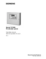
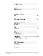
Page 5: ...e1973c 1 02 2004 1 Fire Security Products Siemens Building Technologies Group Introduction ...

Page 6: ...o read an alarm message How to react in an alarm situation 15 Disable Enable System Parts Temporary isolation of a detector zone single detectors i e for repair works Disabling Enabling remote transmission Disabling Enabling alarm devices 21 Faults How to react to a fault message Remedies by the user 31 Maintenance Maintenance works carried out by the user e g Testing detectors Testing lamps batte...

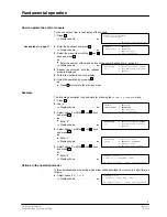
Page 7: ...e1973c 2 02 2004 3 Fire Security Products Siemens Building Technologies Group Fundamentals ...

Page 8: ... activation Reactivation alarm horns Variant 2 1st activation Buzzer off 2nd activation Alarm horns off 3rd activation Reactivation alarm horns Reset key Resets alarm and fault messages Display fields Indicates the operating state by an LED Command fields Possess a button to change the operating mode and may have an LED to indicate the operating state Alarm delay off Cancels alarm delay Remote ala...

Page 9: ...3 4 5 Alarm Fault System ON ALARM zone 1 1 1st floor office 101 ALARM zone 1 1 1st floor office 101 Text display Displays alarm messages Scroll key Allows scrolling of alarm messages in the text display Also to initiate lamp test press key w 3 sec Acknowledge key Confirms an alarm or a message activation Alarm horns and buzzer off Reset key Resets alarm messages Display fields Indicates the operat...

Page 10: ...g permanent or for a set time 1 98h DISabling 1 horn 2 2 2 alarm contacts 3 RT alarm 4 RT fault Disable control line 1 4 for alarm horns Disable alarm contacts 1 4 Disable remote transmission ALARM Disable only event logging or all messages Disable remote transmission FAULT Disable detector ELEMENTS within zone disabling permanent or for a set time 1 98h Disable conTrol zones 1 64 INFO 1 system st...

Page 11: ...NT 1 system status 4 3 2 event memory alarm counter 3 configuration user text 4 configuration zone line LON PRINT 1 fault 4 3 1 2 isolation 3 pre alarm 4 techn alarm element status Print current fault messages Print current turned off system components Print current information messages Print current ELEMENT states PRINT 1 event memory 4 3 2 2 alarm counter Print event memory list Print alarm coun...

Page 12: ...2 ERASE event memory 3 ERASE conf sys data 4 ERASE element status locked with switch S2 not locked to erase non alarm events SERVICE 1 addr line CONNECT level 2 addr line DISCON 4 4 3 3 test AI LED s ON OFF 4 reconfigure addr lines connect addressable loop disconnect addressable loop for TEST LEDs to reconfigure addr lines 5 horn ctrl RT OFF 6 TEST alarm HORN 7 Visualizer ON OFF 8 re parametrise L...

Page 13: ...and press ok or Enter 2 Display shows 4 Select option 1 with the and keys and press ok or Enter 1 Display shows 5 Select option 2 with the and keys and press ok or Enter 2 Display shows Actions in the operation manual In this operation manual selecting a menu item will be described from now on in a short form as follows Select option 2 1 2 Display shows START system operating enter password hm Sto...

Page 14: ...ruption the fire detection system is powered by an internal battery No fault message is issued in the text display and the normal operation will continue until a preset default time is expired When the system is powered by the internal battery the green LED in the display field System on is blinking ALARM System on Fault Isolation Detector test mode FC330A Remote alarm fault off Alarm horn fault o...

Page 15: ...tem parts Poll system information Perform system tests Access level 3 various passwords to di stinguish service engineer or system operator 2 e g se curity officer Edit user text service engineer Service functions Erase data service engineer Application setting Setting passwords Automatic timeout The access by password is automatically cancelled if no key is operated for 5 min during state of norm...

Page 16: ... cancel keying errors Log in 1 Press St Display shows 2 Enter the password and press ok Display shows 3 Proceed operating access is now provided Log out There is no log out procedure because the operating access expires automatically if no key is pressed within a certain time page 11 Automatic timeout START system operating enter password hm Stop end operating SELECT 1 ENabling main menu 2 DISabli...

Page 17: ...stem configuration Operating state unmanned The responsible operating person is not present on the premises The LED in the display field Premises manned is off System on Fault Isolation Detector test mode FC330A Remote alarm fault off Alarm horn fault off System fault Remote alarm active Alarm delay off Premises manned hm 0 del 7 8 9 4 5 6 1 2 3 F1 F2 ok Start Stop 1 Manual switching between the o...

Page 18: ...tic switchover from unmanned to manned at a m Extra time The function extra time allows to set the system to manned operation for a preset time after the automatic switchover to unmanned has taken place 1 Press St Display shows 2 Select option 4 1 1 Display shows The actual display depends on the initial mode here e g mode unmanned i e after 17 00 3 Select option 3 Display shows 4 Enter the extra ...

Page 19: ...e1973c 3 02 2004 15 Fire Security Products Siemens Building Technologies Group Alarm ...

Page 20: ...ons in the event of an alarm Event Action Manual call point is actuated The fire brigade is summoned immediately Automatic fire detector responds The fire brigade is summoned only after a preprogrammed time in which the operating personnel performs following alarm response procedure 1 Confirm the alarm within the alarm acknowledgement time V1 press the Acknowledge key 2 Read the alarm locations on...

Page 21: ...d to the fire department The remaining time is indicated on the text dis play in minutes and seconds Alarm investigation time V2 The alarm investigation time is active for automatic detectors when the system operates in manned mode It limits the time for investigating the fire location to an preprogrammed length On expiration of this time the alarm is transmitted to the fire department In case of ...

Page 22: ...nto the alarm scheme only if the system is in manned mode In all other cases i e SPECIAL Alarm Concept is not activated used or the system operates in unmanned mode the alarm is transmitted immediately to the fire brigade i During alarm other states such as faults etc are not shown at the display However it is possible to make them visible via the menu Info polling For details page 49 ALARM System...

Page 23: ...lement 1 1st floor canteen Scrolling alarm messages Additional pending messages can be retrieved using the scroll key Press the scroll key below the text display The first two lines are superseeded with the subsequent alarm message Retrieving supplementary informations Supplementary informations to the alarm messages can be retrieved by using F1 and F2 F1 tells the type of the responding device e ...

Page 24: ...e1973c 3 02 2004 20 Fire Security Products Siemens Building Technologies Group ...

Page 25: ...e1973c 4 02 2004 21 Fire Security Products Siemens Building Technologies Group Disable Enable System Parts ...

Page 26: ...descriptive user text e g room designation and floor no is defined in the sy stem Only in case of an alarm this text is displayed on the text display together with the zone and device number of the responding detector i It is recommended to prepare a list holding the assignment of zone numbers to actual rooms and building areas When has a detector zone to be isolated In exceptional situations zone...

Page 27: ...abling time in full hours e g 2 Display shows 4 Press St to finish the zone disabling procedure or Enter another zone number to disable Display shows The yellow LED isolation is on SELECT 1 ENabling main menu 2 DISabling 3 INFO polling 4 other functions DISable zones range to zone no 555 all hm back to menu Stop end operating zone SELECTED ok SINGLE zone 2nd zone no range hm back to menu Stop end ...

Page 28: ... 1 Press St Display shows 2 Select option 1 1 1 Display shows The yellow LED isolation is off zone SELECTED hours DISABLED 99 permanent hm back to menu Stop end operating Permanent disabling zone permanent DISABLED hm end new zone no hm back to menu Stop end operating Disabling for a few hours zone DISABLED for hours hm end new zone no hm back to menu Stop end operating parts of system DISABLED to...

Page 29: ...nable all disabled zones 1 Enter 555 to enable all disabled zones no matter if all zones a range of zones or single zones were disabled Display shows With a running timeout after which all zones are automatically enabled 2 Press F1 to enable all zones before the timeout has expired Display shows for a few seconds or 3 Press hm to go back to the submenu Display shows MONITORING zone wait F1 hm enab...

Page 30: ...tified clearly If the detector cannot be identified clearly the whole detector zone should be isolated A wrong isolation of a detector can cause an unwelcome call of the fire brigade Single detector isolation procedure 1 Press St Display shows 2 Select option 2 1 2 Display shows 3 Enter the desired zone number Display shows 4 Enter the desired element number Display shows 5 Enter the desired disab...

Page 31: ...ent number Display shows 5 Enter another element number to ena ble or 6 Press F1 to enable the element before the timeout has expired or 7 Press hm to go back to the submenu SELECT 1 ENabling main menu 2 DISabling 3 INFO polling 4 other functions ENABLE element zone range zone no hm back to menu Stop end operating ENABLE single element in zone element no range timeout hm menu Stop end operating MO...

Page 32: ...ransmission is disabled no automatic alarm is transmitted to the fire department Operating personnel must be on the premises to investigate immediately the location in case of an alarm and to alarm the fire department in case of fire Disabling the remote alarm transmission facility 1 Press St Display shows 2 Select option 2 2 3 Display shows 3 Enter the desired disabling time or 99 for permanent d...

Page 33: ...arm message is pending Enabling the remote fault transmission facility 1 Press St Display shows 2 Select option 1 2 4 Display shows for a few seconds The remote fault transmission is enabled The yellow LED of the display filed Isolation is off if no other parts of the system are isola ted SELECT 1 ENabling main menu 2 DISabling 3 INFO polling 4 other functions RT fault DISABLED timeout hm menu Sto...

Page 34: ... disable or Press St to finish the procedure The desired alarm devices are disabled The yellow LEDs of the display fields Isolation and Alarm horn fault off are on The text display indicates that no alarm message is pending Enabling alarm devices 1 Press St Display shows 2 Select option 1 2 1 Display shows 3 Enter the desired horn number or 555 to enable all horns Display shows for a few seconds 4...

Page 35: ...e1973c 7 02 2004 31 Fire Security Products Siemens Building Technologies Group Faults ...

Page 36: ...splay shows Broken glass on manual call point Display shows Manual call point with broken glass is flashing If a detector is missing insert a detector of the same type into the detector base If a detector is damaged replace it with a detector of the same type and order a new reserve detector from the SIEMENS service organization If a manual call point has been operated and the glass is broken repl...

Page 37: ...e1973c 8 02 2004 33 Fire Security Products Siemens Building Technologies Group Maintenance ...

Page 38: ...manual call points Once every two years i Differing national or local regulations always have priority Recommendations for function tests Perform the function tests periodically The frequency of function tests is determined by the service engineer Switch only the fire detectors of a few zones at a time to detector test mode never the entire building For manual call points the function test needs t...

Page 39: ...rminated for all detector zones Terminating the detector test mode for a zone range 1 Press St Display shows 2 Select option 4 2 3 2 Display shows 3 Enter 0 zero and press ok Display shows for a few seconds The detector test mode is terminated for all detector zones Mode DET TEST zones Outputs NOT activated timeout hm menu Stop end operating Mode DET TEST zones Mode DET TEST range TUE 27 7 99 10 3...

Page 40: ...ctor unit Test procedure for detector tester RE6 1 Set the desired zone into detector test mode page 34 2 Set the detector tester onto the detector and press for 1 second 3 Wait until the response indicator red LED located in the detector housing flashes 4 Possibly press again after 15 20 seconds for 1 second 5 Remove the detector tester The functional testing is completed If the tested detector d...

Page 41: ...S service organization Test procedure for type DIN indirect activation 1 Set the desired zone into detector test mode page 34 2 Open the housing of the manual call point with the key 3 Press down the button completely A test alarm is simulated 4 Observe whether the response indicator a red LED to the right of the button flashes 5 Close the housing The functional testing is completed If the tested ...

Page 42: ...sual and audible devices of the control console are activated for a few seconds Frequency The lamps have to be tested at least once a year Lamp test procedure 1 Press St Display shows 2 Select option 4 2 2 1 To initiate the lamp test Display shows 3 Check all LEDs on buzzer audible missing segments in text display If one or more devices are malfunctional call the SIEMENS service organization i Lam...

Page 43: ...y pack has to be replaced Frequency The batterie test is automatically performed by the system every 24 hours If the battery is dama ged or provides only an insufficent capacity a fault messages is displayed Once a year the battery test has to be performed manually Battery load test procedure 1 Press St Display shows 2 Select option 4 2 2 2 To initiate the battery load test Display shows If the ba...

Page 44: ... acoustic alarm devices have to be tested at least once a year Horn test procedure 1 Press St Display shows 2 Select option 4 2 1 1 To initiate the horn test Display shows The horn test runs for 30 seconds The remaining time is indicated After the test has finished the submenu is displayed again If an acoustic device did not respond in the test call the SIEMENS service organization for repla cemen...

Page 45: ...d After the test has finished the submenu is displayed again If the remote alarm did not arrive at the fire departement call the SIEMENS service organization for repair The test can be stopped before expiration of the 30 seconds by pressing hm Test procedure for remote fault transmission 1 Press St Display shows 2 Select option 4 2 1 4 To initiate the remote FAULT test Display shows The test runs ...

Page 46: ...e1973c 12 02 2004 42 Fire Security Products Siemens Building Technologies Group ...

Page 47: ...e1973c 13 02 2004 43 Fire Security Products Siemens Building Technologies Group Other Functions ...

Page 48: ...l messages Display shows for a few seconds The printer is disabled The yellow LED of the display field Isolation is on Enabling the printer 1 Press St Display shows 2 Select option 1 3 1 Display shows for a few seconds The printer is enabled The yellow LED of the display field Isolation is off if no other parts of the system are isola ted SELECT 1 ENabling main menu 2 DISabling 3 INFO polling 4 ot...

Page 49: ...inst the flap A and feed it through slot C into the printer see picture II 6 Press down the release lever D and shove the paper tape through the printer see picture III 7 Relinquish release lever D The paper can now be transported by means of the knurled wheel E see picture III 8 Feed the paper tape through slot F 9 Thread the leading edge of the paper around the take up roller G and fix it with c...

Page 50: ...n about the number of alarms and remote alarms in the past Polling the alarm counter 1 Press St Display shows 2 Select option 3 2 2 Display shows for a few seconds The submenu is displayed 3 Use St to terminate the alarm counter polling SELECT 1 ENabling main menu 2 DISabling 3 INFO polling 4 other functions ALARM COUNTER alarms remote alarms timeout hm menu Stop end operating ...

Page 51: ... St Display shows 2 Select option 3 2 1 Display shows 3 Use and to scroll through the events The first line tells the event number and the date and time of its occurance the second line reproduces the correspon ding event message Display shows 4 Use hm to go back to the submenu or St to terminate the event memory polling SELECT 1 ENabling main menu 2 DISabling 3 INFO polling 4 other functions view...

Page 52: ...ements 1 Press St Display shows 2 Select option 3 3 3 Display shows 3 Use and to scroll through the zo nes The first line tells the zone number the second and third line reproduces the corresponding user text Display shows 4 Use hm to go back to the submenu or St to terminate the user text polling SELECT 1 ENabling main menu 2 DISabling 3 INFO polling 4 other functions display of USER TEXT for ZON...

Page 53: ...elements are faulty can be retrieved by polling the system status at any time Polling the system status 1 Press St Display shows 2 Select option 3 1 Display shows 3 Select option 1 A scroll page for the selected item is dis played here for example for fault Display shows 4 Use and to scroll through the messages Display shows 5 Use hm to go back to the submenu or St to terminate the system status p...

Page 54: ... 3 4 2 Display shows 3 Enter the desired line number or 555 to select all lines and press ok Display shows 4 Press ok to select only a single line or enter the number of the last line of the desired range and press ok Display shows 5 Use and to scroll through the configuration data of each device of the selected line Display shows 6 Use hm to go back to the submenu or St to terminate the configura...

Page 55: ...shows 3 Select the information to be printed Display shows SELECT 1 ENabling main menu 2 DISabling 3 INFO polling 4 other functions PRINT 1 fault 4 3 1 2 isolation 3 pre alarm 4 techn alarm element status PRINTOUT in process hm stop print Stop end operating SELECT 1 ENabling main menu 2 DISabling 3 INFO polling 4 other functions PRINT 1 event memory 4 3 2 2 alarm counter PRINTOUT in process hm sto...

Page 56: ...fering automatic switching ti mes are not possible Only due to an electronical distortion or a complete power failure mains and battery interrupted the system sets time and date to default Set time and date Log in with at least access level 2 1 Press St Display shows 2 Enter the password and press ok Display shows 3 Select option 4 1 2 Display shows 4 Enter the current time and press ok Display sh...

Page 57: ...Back 02 2004 53 Fire Security Products Siemens Building Technologies Group ...

Page 58: ...y Products Siemens Building Technologies Group Document no Edition e1973c 02 2004 Siemens Building Technologies AG CH 8708 Männedorf Alte Landstrasse 411 Tel Fax www cerberus ch 41 1 922 61 11 41 1 922 64 50 Manual FD M Section 8 ...

Reviews: