background image

TC65 Terminal Hardware Interface Description 
Confidential / Released 

s


TC65 Terminal_HD_V02.000b 

Page 47 of 65 

19.02.2007  


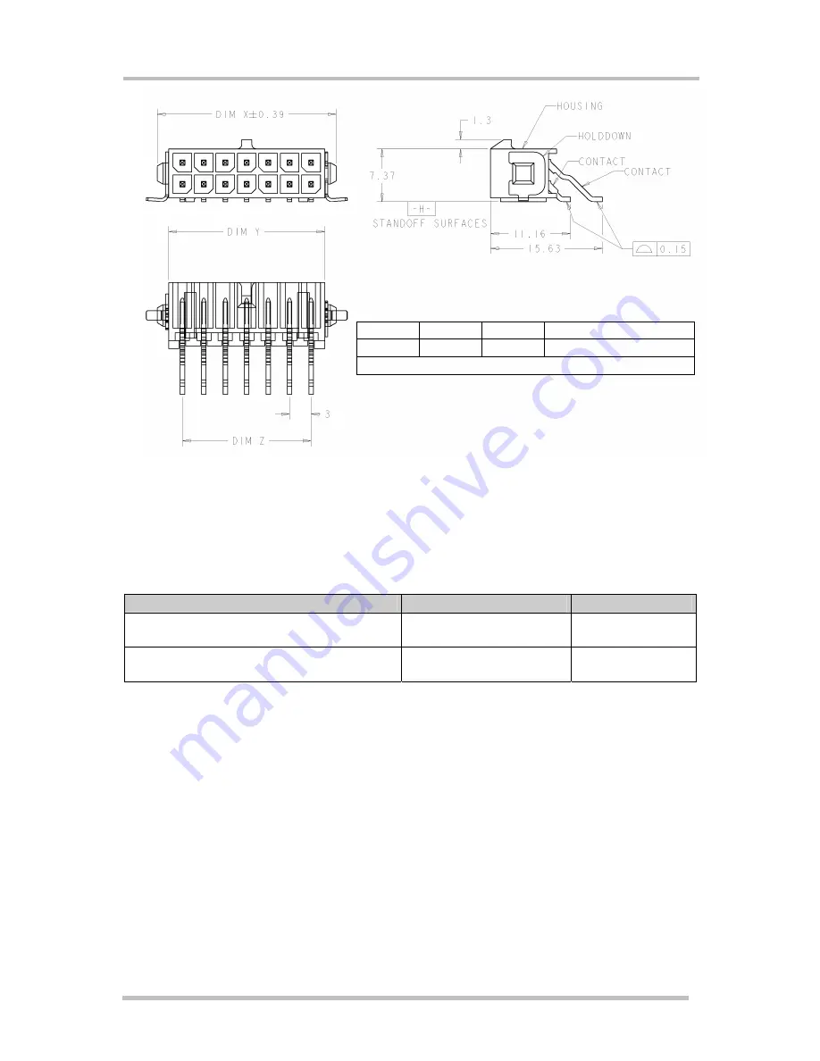
DIM X 

DIM Y 

DIM Z 

Number of Positions 

40.00 36.86 33.00 24 
   Values 

in 

mm 


Figure 18: Mechanical dimensions of the Tyco Mate_N_LOK connector on the TC65 Terminal. 


4.1.1 

Recommended Mating Connector 

Table 20: Ordering information for mating connector Tyco Micro Mate-N-LOK 

Item 

Number of positions 

Ordering number 

Micro Mate-N-LOK 3mm 
 

24 2-794617-4 

Crimp Snap-IN Receptacle Contacts 


794606-* 
794607-* 


Summary of Contents for TC65 Terminal

Page 1: ...Hardware Interface Description TC65 Terminal Siemens Cellular Engine Version 02 000b DocID TC65 Terminal_HD_V02 000b s ...

Page 2: ...the use of mobile technical systems including GSM products which also apply to cellular phones must be followed Siemens or its suppliers shall regardless of any legal theory upon which the claim is based not be liable for any consequential incidental direct indirect punitive or other damages whatsoever including without limitation damages for loss of business profits business interruption loss of ...

Page 3: ...3 5 5 Signal States after Startup 27 3 6 RS 232 Interface 28 3 7 Audio Interface 30 3 7 1 Supported Audio Modes 31 3 7 2 Speech Processing 32 3 8 Antenna Interface 33 3 9 SIM Interface 33 3 10 IO Interface 35 3 10 1 GPIOs 37 3 10 2 Using GPIO Pin10 as Pulse Counter 38 3 10 3 I C Interface 38 3 10 4 SPI Interface 39 3 10 5 Analog to Digital Converter ADC 41 3 10 6 RTC Backup Supply 42 3 10 7 Power ...

Page 4: ...the Pulse Counter 57 5 9 Characteristics of the I2 C interface 58 5 10 Characteristics of the SPI interface 58 5 11 Characteristics of the ADC Interface 59 5 12 Characteristics of the RTC Supply 59 5 13 RF Connector 60 6 Full Type Approval 61 6 1 Siemens Reference Setup 61 6 2 Compliance with FCC Rules and Regulations 62 6 3 Cable Requirements 62 6 4 Restrictions 63 6 5 CE Conformity 63 6 6 Electr...

Page 5: ...tics 44 Table 19 Electrical and mechanical characteristics of the Micro Mate N LOK connector 46 Table 20 Ordering information for mating connector Tyco Micro Mate N LOK 47 Table 21 Absolute maximum ratings 48 Table 22 Operating conditions 49 Table 23 Highest temperatures 49 Table 24 Longest duration until 81 C are reached 50 Table 25 Longest duration when GPRS Class Change does not work properly 5...

Page 6: ...g 4 pole female 30 Figure 8 Audio block diagram 30 Figure 9 Pin location of the Molex SIM card holder and position 33 Figure 10 IO interface connector front view 35 Figure 11 Location of GPIO pins 37 Figure 12 Characteristics of SPI modes 40 Figure 13 ADC balanced amplifier 41 Figure 14 Mechanical dimensions 45 Figure 15 Tyco Micro Mate N LOK series on the TC65 Terminal 46 Figure 16 Mating connect...

Page 7: ...d automotive directive and CE logo Updated list of standards 2 Updated audio features 3 5 5 New chapter Signal States after Startup 3 10 3 10 1 Corrected description of IO interface connector pin 7 and pin 8 Added remark on connecting pull up or pull down resistors to all GPIO pins used as output 3 10 6 Removed possibility to backup RTC from a chargeable external battery 5 1 Changed unit for curre...

Page 8: ...SMS and faxes in GSM networks Industrial standard interfaces and an integrated SIM card reader allow using TC65 Terminal easily as a quad band GSM terminal 1 1 Related Documents 1 TC65 AT Command Set 02 000 2 TC65 Release Notes 02 000 3 Application Note 16 Upgrading TC65 Firmware 4 Multiplexer User s Guide 5 Multiplex Driver Developer s Guide for Windows 2000 and Windows XP 6 Multiplexer Driver In...

Page 9: ...ital level 3 14dBm0 corresponds to full scale see ITU G 711 A law DCE Data Communication Equipment typically modems e g Siemens GSM engine DCS 1800 Digital Cellular System also referred to as PCN DSP Digital Signal Processor DSR Data Set Ready DTE Data Terminal Equipment typically computer terminal printer or for example GSM application DTR Data Terminal Ready DTX Discontinuous Transmission EFR En...

Page 10: ... Terminated NTC Negative Temperature Coefficient PAP Password Authentication Protocol PBCCH Packet Switched Broadcast Control Channel PCB Printed Circuit Board PCM Pulse Code Modulation PCN Personal Communications Network also referred to as DCS 1800 PCS Personal Communication System also referred to as GSM 1900 PDU Protocol Data Unit PPP Point to point protocol PSU Power Supply Unit R TTE Radio a...

Page 11: ... s TC65 Terminal_HD_V02 000b Page 11 of 65 2007 02 19 Abbreviation Description TE Terminal Equipment also referred to as DTE Tx Transmit Direction UART Universal asynchronous receiver transmitter URC Unsolicited Result Code USSD Unstructured Supplementary Service Data ...

Page 12: ...in voltage limits Low Voltage Directive 2002 95 EC Directive of the European Parliament and of the Council of 27 January 2003 on the restriction of the use of certain hazardous substances in electrical and electronic equipment RoHS 2002 96 EC Directive of the European Parliament and of the Council on waste electrical and electronic equipment WEEE 2003 108 EC Directive of the European Parliament an...

Page 13: ...io spectrum Matters ERM Electro Magnetic Compatibility EMC standard for radio equipment and services Part 7 Specific conditions for mobile and portable radio and ancillary equipment of digital cellular radio telecommunications systems GSM and DCS EN 60 950 1 Safety of information technology equipment 2001 Table 4 Requirements of quality IEC 60068 Environmental testing DIN EN 60529 IP codes Table 5...

Page 14: ...s X O O O O O 电缆及电缆组件 Cables and Cable Assemblies O O O O O O 塑料和聚合物部件 Plastic and Polymeric parts O O O O O O O 表示该有毒有害物质在该部件所有均质材料中的含量均在SJ T11363 2006 标准规定的限量要求以下 Indicates that this toxic or hazardous substance contained in all of the homogeneous materials for this part is below the limit requirement in SJ T11363 2006 X 表示该有毒有害物质至少在该部件的某一均质材料中的含量超出SJ T11363 2006标准规定的限量要求 Indicates that this tox...

Page 15: ...s personal subgroup always should check the distance to the mobile Switch off the cellular terminal or mobile before boarding an aircraft Make sure it cannot be switched on inadvertently The operation of wireless appliances in an aircraft is forbidden to prevent interference with communications systems Failure to observe these instructions may lead to the suspension or denial of cellular services ...

Page 16: ...llular signal strength Some networks do not allow for emergency calls if certain network services or phone features are in use e g lock functions fixed dialing etc You may need to deactivate those features before you can make an emergency call Some networks require a valid SIM card to be properly inserted in the cellular terminal or mobile If a power supply unit is used to supply the device it mus...

Page 17: ... Class 1 30dBm 2dB for GSM1900 The values stated above are maximum limits According to Release 99 Version 5 the maximum output power in a multislot configuration may be lower The nominal reduction of maximum output power varies with the number of uplink timeslots used and amounts to 3 0dB for 2Tx 4 8dB for 3Tx and 6 0dB for 4Tx Power supply Single supply voltage 8V to 30V Operating temperature 30 ...

Page 18: ...egration into Java applications ease of programming no need for application microcontroller extremely cost efficient hardware and software design ideal platform for industrial GSM applications The memory space available for Java programs is around 1 7 MB in the flash file system and around 400k RAM Application code and data share the space in the flash file system and in RAM SIM Application Toolki...

Page 19: ...rface Supported SIM cards 3V 1 8V Antenna Connected via antenna SMA connector Power on off Reset Power on Switch on via On Off push button ONOFF line on IO interface connector DTR line at RS232 interface or IGT_IN line at power connector available with recommended power supply Power off Normal switch off by AT SMSO or On Off push button Emergency switch off via EMERGOFF line at power connector Aut...

Page 20: ... requires an appropriate serial adapter to be installed on the computer RF antenna Audio handset Customized mating connector for the IO interface connector type Micro Mate N LOK Terminal program to control the COM port for example Windows HyperTerminal Access to a GSM GPRS network providing support of the authentication protocol PAP CHAP or MS CHAP The GPRS settings of your service provider should...

Page 21: ...ace and antenna 1 24 pole GPIO Micro Mate N LOK connector for GPIOs I C SPI ADC 2 9 pole female SUB D plug for RS 232 serial interface 3 SMA connector female for antenna 4 On Off push button 5 4 pole Western plug female for audio accessory such as a handset 6 SIM card holder 7 6 pole Western plug female for power supply ignition power down signal 1 2 Figure 1 TC65 Terminal front view 3 4 5 6 7 Fig...

Page 22: ... Supply Unit IO connector Application 3 0V Backup Battery RS232 RS232 80 pin B2B RF Audio SIM Power SMA female Step Down DC DC Converter GSM Module TC65 Heat Sink RF Cable SMA Hirose Contact spring Contact spring Votronic Handset or other audio equipment 100V 240V AC Adapter or DC Supply TC65 Terminal TC65T Mainboard Antenna VDD 2 9V or On Off Key 8V 30V In or Out sensors relay unit switches etc 1...

Page 23: ... ready for GPRS data transfer but no data is currently sent or received Power consumption depends on network settings and GPRS configuration e g multislot settings Normal operation GPRS DATA GPRS data transfer in progress Power consumption depends on network settings e g power control level uplink downlink data rates GPRS configuration e g used multislot settings and reduction of maximum output po...

Page 24: ...ole Western Jack SIM Holder 9 pole D Sub female LED blue 80 pole B2B GSM Module TC65 4 0V VDD VDD bypass PWR_IND EN ONOFF DTR d dt EMC GND 1 2 2 1 EMC EMC EMC EMC EMC DTR BACKUP EMC EMERG_OFF EMC 1 On OFF Key VPOS VNEG VNEG lin Reg 2 9V BATT EN VDD VPOS d dt IGT 100u PWR_IND VDD 1 GND VDD PWR_IND 2 EMC EP1 EMC SPIDI SPICS Power 1 1 RF SMA female RF Cable EMC EMC fuse on delay VEXT off 2 10 2 2 2 5...

Page 25: ... ensures an electrical safety according to EN60950 This fuse is not removable A fast acting fuse I 0 8A with melting integral I t 0 8 1 5 A s is necessary to use the TC65 Terminal at a 24V power supply system for vehicles The power supply must be compliant with the EN60950 guidelines Table 8 Pin assignment of the Western plug for power supply Pin Signal name Use 1 POWER Power supply 2 POWER Power ...

Page 26: ...set TC65 Terminal An easy way to reset the TC65 Terminal is entering the command AT CFUN x 1 For details on AT CFUN please see 1 3 5 3 Switch off TC65 Terminal There are several ways to turn off the TC65 Terminal Software controlled shutdown by AT SMSO command The AT SMSO command lets the TC65 Terminal log off from the network and allows the software to enter into a secure state and safe data befo...

Page 27: ...ed state during startup Defined state after initialization GPIO SPI I2 C RXD O L O L TXD I I CTS O H O H RTS I I DTR I I DCD O H O L DSR O H O L RING O L O L SPIDI I Tristate I Tristate SPICS I O H O L Tristate I2CDAT_SPIDO I Tristate O L H IO I2CCLK_SPICLK I Tristate O L H O OD IO1 I PU Tristate IO IO2 I PU Tristate IO IO3 I PU Tristate IO IO4 I PD Tristate IO IO5 O L Tristate IO IO6 I Tristate I...

Page 28: ...multiplexed channels EMC immunity complies with the vehicular environment requirements according to EN 301 489 7 1 2 3 4 5 6 7 8 9 Figure 6 Pin assignment RS 232 D Sub 9 pole female Table 10 9 pole D Sub female RS 232 Pin no Signal name I O Function of application 1 DCD O Data Carrier Detected 2 RXD O Receive Data 3 TXD I Transmit Data 4 DTR I Data Terminal Ready Attention Low to high transition o...

Page 29: ...ves data from RXD of TC65 Terminal The RS 232 interface is implemented as a serial asynchronous transmitter and receiver conforming to ITU T V 24 Interchange Circuits DCE It is configured for 8 data bits no parity and 1 stop bit and can be operated at fixed bit rates from 300bps to 460 800bps Autobauding supports bit rates from 1 2bps to 460 800bps Hardware handshake using the RTS and CTS signals ...

Page 30: ...eference handset for type approval An extra approval must be obtained for integrating other handsets or amplifiers The amplification of sending direction receiving direction and sidetone depends on the current audio mode EMC immunity complies with the vehicular environment requirements according to EN 301 489 7 1 2 3 4 Pin assignment 1 MICN Microphone 4 MICP Microphone 2 EPN Earpiece 3 EPP Earpiec...

Page 31: ... Furthermore the reference parameters are set as factory default In audio mode 4 and 5 the gain in the microphone earpiece and the sidetone path can be adjusted from the cellular device application by using further AT commands Please note that the 2nd audio interface of the TC65 module is not connected in the TC65 Terminal Audio modes 2 3 and 6 can be selected by setting AT SAIC 2 1 1 for further ...

Page 32: ... passed to the speech encoder Received samples from the speech decoder are passed to the DAC after post processing frequency response correction adding sidetone etc Full rate half rate enhanced full rate adaptive multi rate AMR speech and channel encoding including voice activity detection VAD and discontinuous transmission DTX and digital GMSK modulation are also performed on the GSM baseband pro...

Page 33: ...nterface is intended for 3V and 1 8V SIM cards The card holder is a five wire interface according to GSM 11 11 A sixth pin has been added to detect whether or not the SIM card drawer is inserted Removing and inserting the SIM card during operation requires the software to be reinitialized Therefore after reinserting the SIM card it is necessary to restart TC65 Terminal Note No guarantee can be giv...

Page 34: ...by the module 2 CCRST O Chip card reset prompted by the module 3 CCCLK O Chip card clock 4 8 GND Ground 5 CCVPP Not connected 6 CCIO I O Serial data line bi directional 7 CCIN I Chip card drawer detection 0 Chip card drawer inserted 1 Chip card drawer not inserted Input on the baseband processor for detecting the chip card drawer in the holder if the SIM is removed during operation the interface i...

Page 35: ...nector the following interfaces and functions are provided Programmable GPIOs I C bus SPI interface Two analog inputs balanced Power supply Backup supply VDD supply On Off switch of the TC65 Terminal Pulse counter The total cable length of the digital lines for I C and SPI interfaces should not exceed 150mm 24 12 1 13 Figure 10 IO interface connector front view ...

Page 36: ...e GPIO 7 GPIO2 I O Programmable GPIO 8 GPIO1 I O Programmable GPIO 9 ADC2_IN_P I Balanced analog 2 positive input 10 ADC2_IN_N I Balanced analog 2 negative input 11 BACKUP I Backup battery 12 GND Ground for power supply 13 SPICS O SPI Select 14 SPIDI I SPI Data In 15 GPIO9 I O Programmable GPIO 16 GPIO10 I O Programmable GPIO Pulse counter 17 GPIO7 I O Programmable GPIO 18 GPIO8 I O Programmable G...

Page 37: ...unter for an input range of 0 to 1000 pulses per second If the pulse counter is active the pin10 is not available for GPIO signals The GPIOs and the pulse counter can be configured via the following AT commands AT SPIO AT SCPIN AT SCPOL AT SCPORT AT SDPORT AT SGIO AT SSIO AT SCCNT AT SSCNT For details please refer to 1 24 12 1 13 GPIO 3 GPIO 4 GPIO 5 GPIO 6 GPIO 2 GPIO 1 GPIO 9 GPIO 10 GPIO 7 GPIO...

Page 38: ...curacy if you take care that no pulses are transmitted before starting the pulse counter AT SSCNT 0 or 1 and after closing the pulse counter AT SSCNT 3 3 10 3 I C Interface The I C interface is located at the IO interface connector of the TC65 Terminal I C is a serial 8 bit oriented data transfer bus for bit rates up to 400kbps in fast mode It consists of two lines These are the serial data line I...

Page 39: ...w state the SPI bus is activated and data can be transferred from the Terminal and vice versa The SPI interface uses two independent lines for data input SPIDI and data output SPIDO The interface supports transmission rates up to 6 5Mbit s Transfer rates 1 083Mbps and a length of the cable 150mm are not recommended The SPI interface is only available if the pins 1 and 2 of the IO interface connect...

Page 40: ...inal_HD_V02 000b Page 40 of 65 2007 02 19 SPI MODE 0 SPI MODE 1 SPI MODE 2 SPI MODE 3 Clock phase Clock polarity SPICS SPIDO SPICLK SPIDI SPICS SPIDO SPICLK SPIDI SPICS SPIDO SPICLK SPIDI SPICS SPIDO SPICLK SPIDI Sample Sample Sample Sample Figure 12 Characteristics of SPI modes ...

Page 41: ... to configure the analog inputs and to get the measurement results Note It is necessary to recalculate measurement results because an amplifier is used to scale down the ADCx_IN input voltage of the TC65 Terminal 5V to the ADCx_IN input voltage of the in built TC65 module 2 4V Two parameters determined and stored by factory have to be used for offset compensation and for consideration of gain and ...

Page 42: ... the RTC about 6s during power interruptions 3 10 7 Power Supply The two pins of the power supply at the IO interface connector are directly connected to two pins of the Western Jack for power supply This allows supplying the TC65 Terminal by using the Power connector or via the IO interface connector 3 10 8 VDD Supply The VDD pin at the IO interface connector may be used for supplying external ci...

Page 43: ... 43 of 65 2007 02 19 3 11 Status LED A blue LED displays the operating status of the TC65 Terminal The LED can be operated in two different display modes AT SSYNC 1 or AT SSYNC 2 factory default For more information of the different operating states and changing this mode please refer to 1 Status LED ...

Page 44: ...L x W x H 130mm x 90mm x 38mm Temperature range 30 C to 65 C ambient temperature Protection class IP40 Avoid exposing TC65 Terminal to liquid or moisture for example do not use it in a shower or bath Mechanical vibrations Amplitude 7 5mm at 5 200Hz sinus Max pulse acceleration 30g pulse with 18 ms duration time Air humidity 5 80 non condensing Class of flammability UL94 HB Casing material PC ABS C...

Page 45: ...TC65 Terminal Hardware Interface Description Confidential Released s TC65 Terminal_HD_V02 000b Page 45 of 65 2007 02 19 Figure 14 Mechanical dimensions ...

Page 46: ...example http www tycoelectronics com Figure 15 Tyco Micro Mate N LOK series on the TC65 Terminal Figure 16 Mating connector Tyco Micro Mate N LOK series Figure 17 Receptacle contact for Tyco Micro Mate N LOK series Table 19 Electrical and mechanical characteristics of the Micro Mate N LOK connector Parameter Specification Number of contacts 24 Voltage rating 250V Current rating 5A max Resistance 0...

Page 47: ...ons 40 00 36 86 33 00 24 Values in mm Figure 18 Mechanical dimensions of the Tyco Mate_N_LOK connector on the TC65 Terminal 4 1 1 Recommended Mating Connector Table 20 Ordering information for mating connector Tyco Micro Mate N LOK Item Number of positions Ordering number Micro Mate N LOK 3mm 24 2 794617 4 Crimp Snap IN Receptacle Contacts 794606 794607 ...

Page 48: ... V Backup battery BACKUP 4 7 4 7 V On Off line ONOFF No DC Input 0 3 0 3 3 V VDD supply voltage VDD No DC Input 0 3 0 3 1 V Microphone input line AC voltage pins to GND MICP1 MICN1 No DC Input 0 6 1 3 1 2 4 Vpp Earpiece voltage idle no power EPP1 EPN1 No DC Input 0 3 0 3 1 V Antenna Connector No DC input 0 0 V Immunity against air discharge of static electricity All connectors lines 8 8 kV Immunit...

Page 49: ...nt of 15 C the GPRS Class will be stepped up again Continuous operation in Talk mode is possible up to an environmental temperature of about 67 C 12V 900MHz PCL5 With decreasing transmit power of the TC65 Terminal the maximum possible environmental temperature increases at which a GPRS continuous operation at PCL5 Gamma3 is possible For a short time it is also possible to establish a GPRS Class 12...

Page 50: ...mma3 with Power Reduction 7 minutes GPRS Class 12 PCL5 Gamma3 without Power Reduction The following table shows the longest possible duration of connection when the GPRS Class Change from GPRS Class 12 or 10 to GPRS Class 8 did not work properly and 90 C Temperature of Hardware shut off will be reached at the NTC ambient temperature is 65 C Table 25 Longest duration when GPRS Class Change does not...

Page 51: ... Average supply current average time 3 min 25 C worst case GSM 900 max power level Data GPRS 4Tx 1Rx Power reduction 6dB 30V 140 mA 8V 1500 12V 910 IPOWER_P 6 Peak supply current during transmission slot 577µs No of Tx every 4 6ms Power control level for Pout max 30V 340 mA Allowed power fail time without terminal reset or power down After this time the Terminal will be reset or switched off 1 ms ...

Page 52: ...ll be lost if used the emergency off If unused keep pin open IGT_IN I RI 100kOhm CI 100nF VLmax 0 8V VLmin 0 3V VHmin 8V VHmax 30V signal ___________ __ 0 5s 0 5s Rise time 100ms This signal switches the mobile ON It s possible to connect IGT_IN directly with POWER If unused keep pin open Ignition ONOFF I RI 30kΩ CI 10nF VILmax 0 5V at Imax 150µA VOHmax 4 2V ON OFF ________ ________ 0 4s 2s 1s Ris...

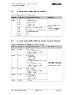
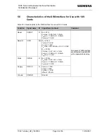
Page 53: ...e to start the module with DTR 5 4 Characteristics of the SIM Interface for Use with 3V Cards Table 29 Characteristics of the SIM interface for use with 3V cards Function Signal name IO Signal form and level Comment Reset CCRST O RO 47Ω VOLmax 0 25V at I 1mA VOHmin 2 5V at I 0 5mA VOHmax 2 95V Data IO CCIO I O RI 4 7kΩ VILmax 0 75V VILmin 0 3V VIHmin 2 1V VIHmax CCVCCmin 0 3V 3 05V RO 100Ω VOLmax ...

Page 54: ...rm and level Comment Reset CCRST O RO 47Ω VOLmax 0 25V at I 1mA VOHmin 1 45V at I 0 5mA VOHmax 1 90V Data IO CCIO I O RI 4 7kΩ VILmax 0 45V VIHmin 1 35V VIHmax CCVCCmin 0 3V 2 00V RO 100Ω VOLmax 0 3V at I 1mA VOHmin 1 45V at I 0 5mA VOHmax 1 90V Clock CCCLK O RO 100Ω VOLmax 0 3V at I 1mA VOHmin 1 45V at I 0 5mA VOHmax 1 90V Supply CCVCC O VOmin 1 70V VOtyp 1 80V VOmax 1 90V IOmax 20mA Ground CCGND...

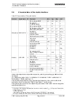
Page 55: ...equency area 200 3900 Hz DC Offset balanced 100 mV Attenuation distortion for 200 3900Hz 1 dB Earpiece EPP EPN O Out of band discrimination 70 dB LEAudio Length of Audio Handset cable 3 m Unless otherwise stated all specified values are valid for gain setting gs 0dB and 1kHz test signal gs 0dB means audio mode 5 inBbcGain 0 inCalibrate 32767 outBbcGain 0 OutCalibrate 16384 sideTone 0 The electrica...

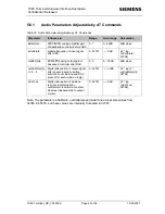
Page 56: ...67 0dB 20 log inCalibrate 32768 outBbcGain EPP EPN analog output gain of baseband controller after DAC 0 3 0 18dB 6dB steps outCalibrate n n 0 4 Digital attenuation of output signal after speech decoder before summation of sidetone and DAC present for each volume step n 0 32767 6dB 20 log 2 outCalibrate n 32768 sideTone Digital attenuation of sidetone is corrected internally by outBbcGain to obtai...

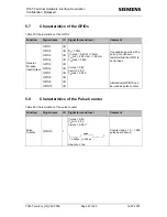
Page 57: ... O I O I O I O I O I O RO 100Ω VOLmax 0 4V at I 2mA VOHmin 2 50V at I 0 5mA VOHmax 3 05V VILmax 0 8V VIHmin 2 0V VIHmax 3 05V If unused keep pins with a pull up or pull down resistor while the GPIO is set to input Alternatively GPIO10 can be used as pulse counter 5 8 Characteristics of the Pulse Counter Table 34 Characteristics of the pulse counter Function Signal name IO Signal form and level Com...

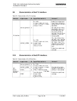
Page 58: ...rsion 2 1 for the fast mode a rise time of max 300ns is permitted There is also a maximum VOL 0 4V at 3mA specified The value of the pull up depends on the capacitive load of the whole system I2C Slave lines The maximum sink current of I2CDAT and I2CCLK is 4mA If lines are unused keep pins open 5 10 Characteristics of the SPI interface Table 36 Characteristics of the SPI interface Function Signal ...

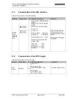
Page 59: ...x_IN_P positive voltage VI min 0V VI max 5V Ri single ended 600kOhm Ri balanced 1200kOhm Cut off frequency fg 70Hz Common mode rejection ratio CMRR 50dB Inaccuracy 1mV Linear error 1mV Temperature error 1mV Burst error 1mV ADC1_IN and ADC2_IN are balanced lines and multiplexed with an analog switch Both inputs are filtered by a low pass 5 12 Characteristics of the RTC Supply Table 38 Characteristi...

Page 60: ...4 MHz GSM 900 880 1785 MHz GSM 1800 1710 1880 MHz Frequency range GSM 1900 1850 1990 MHz EGSM 850 102 dBm GSM 900 102 dBm GSM 1800 102 dBm Receiver input Sensitivity antenna connector Under all propagation conditions according to GSM Spec GSM 1900 102 dBm EGSM 850 102 105 dBm GSM 900 102 105 dBm GSM 1800 102 105 dBm Receiver input Sensitivity antenna connector BER Class II 2 43 static input level ...

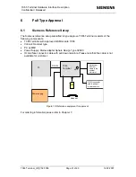
Page 61: ...65 Terminal with approved GSM module TC65 Votronic Handset type PC as MMI Power Supply Mains adapter Sphere Design Type 39020 IO interface connector cable with pull down resistors Please note that this cable is not available for customer PC Power supply SIM RS 232 TC65 Terminal Handset Antenna or 50 Ohm cable to the system simulator ARP GPIO connector cable with pull down resistors Figure 19 Refer...

Page 62: ...ons The antenna s used for this transmitter must be installed to provide a separation distance of at least 20cm from all persons and must not be co located or operating in conjunction with any other antenna or transmitter Users and installers must be provided with antenna installation instructions and transmitter operating conditions for satisfying RF exposure compliance Antennas used for this OEM...

Page 63: ...ty The TC65 Terminal meets the requirements of the EU directives listed below R TTE Directive 1999 5 EG LVD 73 23 EEC EMC conformity in accordance with Directive 89 336 EEC 6 6 Electromagnetic Compatibility EMC The TC65 Terminal meets EN 301489 7 requirements of equipment for vehicular and fixed use Note VPOWER voltage dip or interruption corresponding to a reduction of the supply voltage of 30 fo...

Page 64: ...re Design Saarpfalz Park 17 D 66450 Bexbach Saar Phone 49 6826 5200 0 Fax 49 6826 5200 25 E Mail info spheredesign de http www spheredesign de Handset Votronic Ordering number HH SI 30 3 V1 1 0 Votronic GmbH Saarbrücker Str 8 D 86386 St Ingbert Phone 49 6894 9255 44 Fax 49 6894 9255 88 Antenna Magnet Mount US GSM 850 GSM 1900 EU GSM 900 GSM 1800 Direct Mount US GSM 850 GSM 1900 EU GSM 900 GSM 1800...

Page 65: ...In contacts 794606 or 794607 24 pieces housing for full assembly Hand Tool CERTI CRIMP II Straight 91501 1 http www tycoelectronics com cust stm Rail Clip Firma Richard Wöhr GmbH Ordering number Hutsclip AL 0002 Richard Wöhr GmbH Gräfenau 58 60 D 75339 Höfen Enz Phone 49 7081 9540 0 Fax 49 7081 9540 90 E Mail info ig woehrgmbh de http www industriegehaeuse woehrgmbh de Screws for Rail Clip EJOT Gm...

Reviews: