Clamp Removal
1. Refer to Figure 7 for parts identification. Loosen nut J and
remove bolt H, washer I and nut from riser.
2. Loosen nut D and remove bolt B, washer C and nut from the
clamp assembly.
3. Remove tie bar and clamp assembly simultaneously.
4. Repeat steps 1 - 4 for each phase.
Clamp Assembly
1. Connect tie bar to riser by sliding bolt H through tie bar and
riser. Fasten with washer I and torque nut J to bolt H secur-
ing to 21 ft.-lbs.
2. Loosely assemble the clamp assembly, making sure that
clamp spring E will compress against bar F, when the bolt is
drawn tight.
3. Slide carriage bolt B through the one side of the clamp
assembly and tie bar until it protrudes through the other side
of the clamp assembly. Fasten with washer C and torque
nut D to bolt B securing to 21 ft.-lbs.
4. Repeat steps 1 - 3 for all phases.
6
Siemens Energy & Automation, Inc.
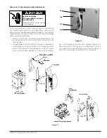
Figure 4
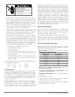
Note: The white side of clamping spring should be visible on outside
of each assembly.
Hazardous voltage.
Can cause death, serious personal
injury, or property damage.
Disconnect power before working on this
equipment.
Bus Overload
May cause hazardous over heating.
Vertical bus must be rated for 600A.
Figure 5
-
Fixed Mounted Panel Diagram
Summary of Contents for TIASTAR SFIM-70020
Page 63: ......
Page 64: ......
Page 65: ......
Page 66: ......
Page 67: ......
Page 68: ......
Page 69: ......
Page 70: ......
Page 71: ......
Page 72: ......
Page 73: ......
Page 74: ......
Page 75: ......
Page 76: ......
Page 77: ......
Page 78: ......
Page 79: ......
Page 80: ......
Page 81: ......
Page 82: ......
Page 83: ......
Page 84: ......
Page 85: ......
Page 86: ......
Page 87: ......
Page 88: ......
Page 96: ...4 ...
Page 100: ...5 Today and tomorrow you ll know you have the very best ...
Page 115: ...13 Siemens Energy Automation Inc ...
Page 116: ...14 Siemens Energy Automation Inc ...
Page 117: ...15 Siemens Energy Automation Inc ...


