background image


The Web server (WBM) 


6.10 Logging 

TIM 1531 IRC 
Operating Instructions, 02/2018, C79000-G8976-C468-02 

279


6.9.2


Data points 

The tab shows you information on the configures data points of the TIM. 

Data points 


Data point number 


Name & type 
Name and type of the data point 


Type identifier 
Object group/Type of data point 
Only relevant for DNP3/IEC 


Object number 
Object number of the ST7 data point 


Status 
Status of the assignment (connection) of the data point to a communication partner 


Current value 
Currently saved value 


Historical value 
Previous value 


Time stamp 
Time stamp of the currently saved value 

6.10


Logging 

Functions of logging 

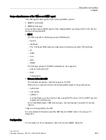
On this page, you can log the data traffic of the TIM using PCAP functionality for diagnostics 

purposes. 
If an error occurs or if the TIM behaves in an unwanted manner, the communication behavior 

of the TIM can be recorded. The frame traffic of the TIM is recorded for a defined time or for 

a configurable number of frames. 
The log files are stored as PCAP files on the connected PC and can be evaluated with the 

Wireshark program, for example. 

Summary of Contents for TIM 1531 IRC

Page 1: ..._________________ SIMATIC NET S7 1500 TeleControl TIM 1531 IRC Operating Instructions 02 2018 C79000 G8976 C468 02 Preface Application and functions 1 LEDs connectors switches card slot 2 Installation connecting up commissioning 3 Configuration 4 Block library TeleControl ST7 5 The Web server WBM 6 Diagnostics and upkeep 7 Technical specifications 8 Approvals 9 Dimension drawings A Accessories B S...

Page 2: ...e operated only by personnel qualified for the specific task in accordance with the relevant documentation in particular its warning notices and safety instructions Qualified personnel are those who based on their training and experience are capable of identifying risks and avoiding potential hazards when working with these products systems Proper use of Siemens products Note the following WARNING...

Page 3: ...ocol with three RJ 45 interfaces for communication via IP based networks WAN LAN and an RS 232 RS 485 interface for communication via classic WAN networks Figure 1 TIM 1531 IRC You will find the the article number of the device on the top right of the housing You will find the hardware product version of the device printed as a placeholder X on the right of the device for example X 2 3 4 In this c...

Page 4: ...projects configured in STEP 7 V5 to STEP 7 Professional PG routing Editorial revision Replaced manual edition Edition 05 2017 Required experience To install commission and operate the device you require experience in the following areas Setting up industrial networks with security functions Data transfer via WAN networks SIMATIC STEP 7 Professional Abbreviations acronyms This manual often uses the...

Page 5: ...eration of plants systems machines and networks In order to protect plants systems machines and networks against cyber threats it is necessary to implement and continuously maintain a holistic state of the art industrial security concept Siemens products and solutions constitute one element of such a concept Customers are responsible for preventing unauthorized access to their plants systems machi...

Page 6: ...c Equipment Do not dispose of the product at public disposal sites For environmentally friendly recycling and the disposal of your old device contact a certified disposal company for electronic scrap or your Siemens contact Keep to the local regulations You will find information on returning the product on the Internet pages of Siemens Industry Online Support Link https support industry siemens co...

Page 7: ...and those to be expanded 28 1 9 2 Requirements for the expansion 29 2 LEDs connectors switches card slot 31 2 1 Overview LEDs connectors switches card slot 31 2 2 LEDs 32 2 3 Electrical connectors 33 2 3 1 Ethernet interfaces X1 X2 X3 33 2 3 2 Serial interface X4 34 2 3 3 X80 External power supply 34 2 4 Switch 35 2 5 SD card slot 37 3 Installation connecting up commissioning 39 3 1 Important note...

Page 8: ... options 67 4 9 2 1 MSC protocol settings 67 4 9 2 2 TCP connection monitoring 71 4 9 2 3 Transmission settings 71 4 9 3 Web server access 72 4 10 Serial interface Advanced options 72 4 10 1 MSC settings 72 4 10 2 Dedicated line 72 4 10 3 Dialup network 75 4 11 Web server 79 4 12 Partner stations 80 4 13 Communication with the CPU 81 4 14 Time of day synchronization 85 4 15 Time stamp 89 4 16 MSC ...

Page 9: ...T 140 5 6 2 1 SDTs 140 5 7 Master copies 141 5 7 1 Data point typicals 141 5 7 1 1 Types and overview of the data point typicals 141 5 7 1 2 Reoccurring parameters 144 5 7 1 3 Time stamp 154 5 7 1 4 Analog value typical Ana04R_S 155 5 7 1 5 Analog value typical Ana04R_R 159 5 7 1 6 Analog value typical Ana04W_S 160 5 7 1 7 Analog value typical Ana04W_R 167 5 7 1 8 Binary value typical Bin04B_S 168...

Page 10: ...5 7 3 7 FC Startup 258 5 7 4 Communication blocks BCom CPU1500 258 5 7 4 1 FB BCom 258 5 7 4 2 BConnect FB 258 5 7 4 3 DB BConnectData 259 5 7 5 Communication blocks BCom CPU400 259 5 7 5 1 FB BCom 259 5 7 5 2 DB BComData 260 5 7 6 Communication blocks PCom CPU300 260 5 7 6 1 FB PCom 260 5 7 6 2 DB PComData 260 5 7 7 Communication blocks XCom CPU300 261 5 7 7 1 FB XCom 261 5 7 7 2 DB XComData 261 ...

Page 11: ...nical specifications 293 8 1 Technical specifications 293 8 2 Pinout of the Ethernet interfaces 295 8 3 Pin assignment of the serial interface 296 9 Approvals 297 A Dimension drawings 301 B Accessories 303 B 1 Power supply 303 B 2 SD cards 303 B 3 Routers modems antennas 305 B 3 1 Dedicated line and dialup network modems 305 B 3 2 MODEM MD720 306 B 3 3 Router SCALANCE M 307 B 3 4 Mobile wireless a...

Page 12: ...Table of contents TIM 1531 IRC 12 Operating Instructions 02 2018 C79000 G8976 C468 02 C 5 Exporting configuration data 316 D Documentation references 319 Glossary 323 Index 337 ...

Page 13: ...ent on the S7 device family or rack type of the assigned CPU For the telecontrol communication the TIM uses the SINAUT ST7 protocol Due to the capability of the TIM to establish redundant transmission paths between stations and to the master station and the option of storing process values the communication has a high degree of reliability Master station types As the connection partner of the TIM ...

Page 14: ...nfiguration You will find the supported transmission protocols and network types in the section Communications services Page 14 Network node types With its four interfaces the TIM can used at the following positions of a WAN network Master station Node station Station Expansion of existing SINAUT systems In existing SINAUT systems with SIMATIC S7 300 400 stations and TIM modules for the telecontro...

Page 15: ...on between the subscribers Inter station communication In dedicated line networks and with communication via the Internet with a mobile wireless network GSM MSC the TIM supports inter station communication between S7 stations via the master station With inter station communication the TIM establishes a connection to the master station The master station forwards the messages to the destination sta...

Page 16: ...nication via mobile wireless and the Internet DSL using a SCALANCE M mobile wireless router For a description of the protocols refer to the section Security functions Page 18 S7 communication For reading writing data from and to the local CPU via S7 connections the following services are supported PG communication Communication with an engineering station PG routing S7 communication across subnetw...

Page 17: ...ed media A requirement for the CPs is that the options S7 communication and Online functions are enabled in the Communication types parameter group Module Medium protocol TIM 1531 IRC TIM 4R IE TIM 3V IE TIM 3V IE Advanced CP 1243 8 IRC CP 1542SP 1 IRC TIM 1531 IRC Ethernet S7 Ethernet MSC RS 232 Ethernet S7 Ethernet MSC Ethernet S7 Ethernet MSC Ethernet S7 Ethernet S7 TIM 4R IE Ethernet S7 Ethern...

Page 18: ...password In addition to this the shared automatically generated key is renewed between the communications partners at a configurable Key exchange interval Further security functions of the TIM The TIM also supports the following security functions NTP secure For secure transfer during time of day synchronization STARTTLS SSL TLS For the secure transfer of e mails HTTPS For secure access to the Web...

Page 19: ...l packet inspection layer 3 and 4 Firewall also for non IP Ethernet frames according to IEEE 802 3 layer 2 Limitation of the transmission speed to restrict flooding and DoS attacks Define IP packet filter rules Global firewall rule sets Protection for devices and network segments The protection provided by the firewall can cover individual devices several devices or even entire network segments Co...

Page 20: ...the SD card IP configuration The TIM supports IP addresses according to IPv4 Address assignment The IP address the subnet mask and the address of a gateway can be set manually in the configuration As an alternative the IP address can be obtained from a DHCP server or by other means outside the configuration Time of day synchronization On every interface the TIM provides the option of receiving and...

Page 21: ...he station is located in the same IP subnet The following online functions are available Downloading project or program data from the STEP 7 project to the station Querying diagnostics data on the station Downloading firmware files to the TIM SNMP As an SNMP agent the TIM supports data queries using SNMPv1 and SNMPv3 Simple Network Management Protocol For more detailed information refer to section...

Page 22: ...TIM Figure 1 2 Communication via Ethernet Internet E mails The TIM can generate and send e mails due to events The following recipients are possible PCs with an Internet connection Mobile phones SIMATIC stations with the appropriate program blocks Inter station communication Inter station communication between S7 stations with a TIM is possible via IP based and WAN networks Inter station communica...

Page 23: ...erfaces are used Ethernet interface for communication via Ethernet Internet The TIM modules use the transmission protocol MSC or MSCsec Serial interface for communication via a WAN network dedicated line or dialup network Figure 1 3 Communication via redundant paths Telecontrol communication via mobile wireless and wireless networks Mobile wireless In these examples the TIM modules of the master c...

Page 24: ...less networks The left station TIM is configured as a node station Underlying this an analog wireless network with several stations is connected via the serial interface An IP based wireless network could also be connected via the Ethernet interface Figure 1 4 Communication using mobile wireless at the top and wireless at the bottom ...

Page 25: ...ons or 127 MSC connections Ethernet X2 62 S7 connections Ethernet X3 62 S7 connections Serial X4 32 Dedicated line 32 partners Dialup network 32 partners Node station Ethernet X1 32 TCP 16 S7 connections or 1 MSC connection Ethernet X2 16 S7 connections Ethernet X3 16 S7 connections Serial X4 16 Dedicated line 16 partners Dialup network 16 partners E mail SMS At runtime a connection can be establi...

Page 26: ...e of 100000 messages The size of the message memory is divided equally among all configured communications partners You will find details of how the send buffer works storing and sending events as well as the options for transferring data in the section Process image type of transmission event classes Page 113 You can set saving of frames on an optional SD card in the configuration see section Con...

Page 27: ...equired STEP 7 Professional V15 0 The following configuration tool is required to configure the proxy module in STEP 7 V5 to expand SINAUT systems STEP 7 V5 6 together with SINAUT engineering software V5 5 SP3 1 8 2 Usable CPUs Compatible CPUs The following can be used as the local CPU of the TIM S7 1500 All CPUs that can be configured in STEP 7 as of firmware version V2 1 S7 300 All CPUs that can...

Page 28: ...TIM 4R IE TIM 4R IE Stand alone STEP 7 Profession al CP 1243 8 IRC V3 0 CP 1243 8 IRC STEP 7 Basic TIM 1531 IRC V1 0 TIM 1531 IRC STEP 7 Profession al CP 1542SP 1 IRC V2 0 CP 1542SP 1 IRC STEP 7 Profession al Extension of existing SINAUT projects in the TIA Portal SINAUT projects with TIM modules for the SIMATIC S7 300 and S7 400 series which were configured in STEP 7 V5 can be extended with commu...

Page 29: ...tion for STEP 7 V5 project ex pansion S7 1200 1500 module in STEP 7 Basic Professional TIM function for expansion Proxy to be used in the catalog Compatible module Required STEP 7 version TIM 3V IE Advanced PROXY CP1243 8 IRC CP 1243 8 IRC STEP 7 Basic TIM 4R IE PROXY TIM 1531 IRC TIM 1531 IRC STEP 7 Professional TIM 4R IE Stand alone PROXY TIM 1531 IRC TIM 1531 IRC STEP 7 Professional Note TIM 4R...

Page 30: ...ion of the data from STEP 7 V5 without the option of making changes A physical V2 1 CP can be exchanged for a V3 1 CP but not the other way round The CP used must have hardware product version 2 The existing data is adopted Requirements TIM 1531 IRC Communication partner of the TIM 1531 IRC Requirements for importing ST7 connections between a TIM 1531 IRC and a CPU 1500 The CPU 1500 must have at l...

Page 31: ...Receptacle for SD card X80 Power supply socket Status and diagnostics LEDs covered RUN ERROR CONNECT X1 Ethernet interface Gigabit Ethernet Article number covered X2 Ethernet interface Fast Ethernet Switch X3 Ethernet interface Fast Ethernet MAC address Ethernet interface X2 Serial number 2D matrix code alphanumeric MAC address Ethernet interface X1 MAC address Ethernet interface X3 X4 Serial inte...

Page 32: ...rnet interface X1 X2 and X3 The LED symbols have the following meaning Table 2 2 Legend for the tables Symbol Meaning LED status ON LED lit OFF LED flashes Any Status and diagnostics LEDs Table 2 3 Meaning of the LED patterns in productive operation RUN yel low green ERROR red CONNECT green Meaning No supply voltage or supply voltage too low TIM in RUN mode TIM in STOP mode TIM in maintenance stat...

Page 33: ...3 yellow green Meaning No connection to the Ethernet network Ethernet connection without data transfer Ethernet connection with data transfer 2 3 Electrical connectors 2 3 1 Ethernet interfaces X1 X2 X3 Ethernet interfaces The Ethernet connectors are located behind the cover of the enclosure The interfaces are RJ 45 jacks according to IEEE 802 3 Note Connection to subnets The three Ethernet interf...

Page 34: ...96 2 3 3 X80 External power supply External power supply The connector X80 socket for the external 24 VDC power supply is located on the front of the TIM The power supply is connected to the TIM with the supplied plug in terminal block The plug in terminal block is designed so that it can only be plugged in in one position in the X80 socket of the TIM The connector X80 has electronic reverse polar...

Page 35: ...UN mode This is the basic setting for productive operation STOP STOP mode Set the TIM to STOP before disconnecting the power supply Setting to STO may also be necessary if an error fault occurs to be able to restart the TIM afterwards In STO mode the following functions are disabled Telecontrol operation of the TIM Time of day synchronization via Telecontrol connections S7 connections are terminat...

Page 36: ...IM is reset to the factory settings Note the effects of the reset particularly the deletion of the configuration data For information on the effects of resetting refer to the section Resetting to factory settings Page 287 Functions in the setting MRES Functions when holding the switch in the MRES setting for at least 5 seconds Table 2 6 Button functions Function Previous setting or action Effect R...

Page 37: ...ts configured as an event An SD card does not ship with the TIM Compatible cards You will find a list of compatible SD cards in the appendix SD cards Page 303 Use one of the SD cards listed there The minimum size is 24 MB If you use an SD card with less storage space it is possible that not all process data see below can be saved retentively Card errors diagnostics Card errors are indicated by ent...

Page 38: ... the new TIM the configuration data can be made available to the new TIM In this case you do not need an engineering station with a STEP 7 project The configuration data is saved on the SD card when the TIM starts up For information on device replacement refer to section Module replacement Page 292 Process data You have the option of storing values of data points configured as an event This serves...

Page 39: ... inner temperature of the cabinet corresponds to the ambient temperature of the device Overvoltage protection NOTICE Protection of the external power supply If power is supplied to the module or station over longer power cables or networks the coupling in of strong electromagnetic pulses onto the power supply cables is possible This can be caused for example by lightning strikes or switching of hi...

Page 40: ...4 1 WARNING EXPLOSION HAZARD Do not connect or disconnect cables to or from the device when a flammable or combustible atmosphere is present WARNING When used in hazardous environments corresponding to Class I Division 2 or Class I Zone 2 the device must be installed in a cabinet or a suitable enclosure WARNING If a device is operated in an ambient temperature of more than 60 to 70 C the temperatu...

Page 41: ...precautions must be taken If the equipment is operated in an air ambient in excess of 50 C only use cables with admitted maximum operating temperature of at least 80 C WARNING Take measures to prevent transient voltage surges of more than 40 of the rated voltage This is the case if you only operate devices with SELV safety extra low voltage WARNING LAN connection Local Area Network A LAN or LAN se...

Page 42: ...nt WARNING Explosion hazard Do not disconnect equipment when a flammable or combustible atmosphere is present WARNING EXPLOSION HAZARD The equipment is intended to be installed within an ultimate enclosure The inner service temperature of the enclosure corresponds to the ambient temperature of the module Use installation wiring connections with admitted maximum operating temperature of at least 30...

Page 43: ...e specified Installation in a suitable cabinet Installation in a suitable enclosure Installation in a suitably equipped enclosed control room WARNING Cable temperatures If the cable or housing socket exceeds 70 C or the branching point of the cables exceeds 60 C special precautions must be taken If the equipment is operated in an ambient environment in excess of 40 C only use cables with permitted...

Page 44: ...TIM so that its upper and lower ventilation slits are not covered allowing adequate ventilation as protection from overheating Keep to the following minimum clearances for the circulation of air when the rack is installed horizontally Above the TIM At least 33 mm Below the TIM At least 25 mm Installation of the rack Installation position of the modules Horizontal installation of the rack Vertical ...

Page 45: ... installation in the SIMATIC S7 1500 ET 200MP Manual Collection see 2 Page 319 Removal from the DIN rail Follow the steps below to remove the TIM from the DIN rail 1 Switch the TIM to STOP 2 Turn off the power supply to the TIM 3 Pull off the Ethernet cables and the serial bus 4 Release the securing screws of the TIM 5 Tilt the TIM out of the standard rail 3 3 Wiring WARNING Power supply The devic...

Page 46: ...wer supply cable if you use a voltage source according NEC Class 2 or a power supply from the range of accessories see attachment Power supply Page 303 Order of the work NOTICE Connection only with power off Only connect the TIM with the power switched off The device can be disconnected from the power supply with the terminal block Requirement The TIM is mounted 1 Connect the external power supply...

Page 47: ... following pin assignment for the X80 socket Terminal Assignment L 24 VDC M Ground You will find information about the connectable cable cross sections power consumption and further technical details in section Technical specifications Page 293 RS 485 Connection of the terminating resistor If you connect a star shaped network with several dedicated line or dialup network modems to the serial inter...

Page 48: ...the section Configuration Page 51 The STEP 7 project with the TIM is open on the engineering station For loading the engineering station is connected to an Ethernet interface of the TIM Downloading the configuration data To start productive operation the TIM requires the STEP 7 configuration data To download the configuration data follow the steps outlined below 1 Change the switch of the TIM to t...

Page 49: ...Meaning LED status ON LED lit OFF LED flashes Any The table below describes the LED patterns in the individual startup phases of the TIM Table 3 2 Meaning of the LED patterns at startup Startup phase RUN yel low green ERROR red CONNECT green Meaning 1 Hardware initialization and downloading the operating system 2 Downloading the firmware 3 Downloading the configuration data 4 Startup successful st...

Page 50: ...Installation connecting up commissioning 3 6 Startup LED pattern TIM 1531 IRC 50 Operating Instructions 02 2018 C79000 G8976 C468 02 ...

Page 51: ...an find information on Industrial Security here Link http www siemens com industrialsecurity You can find information on security in industrial communication here Link http w3 siemens com mcms industrial communication en ie industrial ethernet security Seiten industrial security aspx You can find a publication on the topic of network security 6ZB5530 1AP02 0BA5 here Link http w3app siemens com mcm...

Page 52: ...rity Only use passwords with a high password strength Avoid weak passwords for example password1 123456789 or similar Make sure that all passwords are protected and inaccessible to unauthorized personnel See also the preceding section for information on this Do not use one password for different users and systems Protocols Secure and non secure protocols Only activate protocols that you require to...

Page 53: ...s closed because the TIM is always client for this service Authentication Specifies whether or not the protocol authenticates the communications partner during access Protocol function Port number pro tocol Default of the port Port status Authentication S7 and online connections 102 TCP Open Open No HTTP 80 TCP Closed Open after configuration No HTTPS 443 TCP Closed Open after configuration Yes SN...

Page 54: ...llowing steps 1 Create a STEP 7 project with security functions activated Note Activated security functions If you have not yet activated any security functions or have logged on in Global security settings you first need to log on as a security user The configuration of the TIM is only possible with activated security functions Also for access to the Web server of the TIM the users must be create...

Page 55: ...ation system Copy functions for larger projects The copying functions of STEP 7 reduce configuration effort Use the copying functions in particular with large projects with several identical or similar stations Copying devices and stations If you use several similar TIM modules or CPUs in a project it is advisable to configure the first device first and then to copy the entire configuration data T...

Page 56: ...WAN networks IP based WAN networks Subscriber types The following subscriber types that support the ST7 protocol are possible communications partners SIMATIC stations with TIM modules or a CP capable of ST7 Control center applications capable of ST7 Connections Communication with the ST7 protocol runs via configurable connections You make the required settings in the STEP 7 configuration Communica...

Page 57: ...y a connection is seldom established you can test the reachability via this path for example by synchronizing the time of day once daily via this path To do this a connection must be established once daily via the dialup network The reachability is then updated once daily in the PLC tag Addressing communications partners and network nodes Since the communication between two ST7 subscribers can run...

Page 58: ... address is configured in the parameter group WAN parameters of the serial interface 4 4 Basic settings 4 4 1 Configuration Telecontrol configuration This is where you specify whether you want to freely configure the module or whether you want to import the configuration data of a proxy module to expand a STEP 7 V5 project Configure The subscriber data and SINAUT connections are configured in the ...

Page 59: ...nts are saved is specified in the configuration of the individual data point in the Trigger tab see section Data points Page 104 For the maximum number of savable messages see section Performance data and configuration limits Page 25 4 5 Overview Connection to LAN WAN Transfer options The interfaces of the TIM support the following network types and protocols Ethernet interfaces IP based Communica...

Page 60: ...C MSCsec DSL router TIM SCALANCE M MSCsec SCALANCE M TIM SCALANCE M VPN SCALANCE M TIM IP wireless network IP wireless modem IP IP wireless modem TIM Dedicated line Dedicated line mo dem RS 232 RS 485 Dedicated line modem TIM Analog wireless mo dem Analog wireless modem Analog dial up network Dial up network mo dem V 32bis V 34bis Dial up network modem TIM ISDN dial up network ISDN modem ISDN ISDN...

Page 61: ...via a new subnet Connecting devices to existing subnet Selecting an existing subnet from the Subnet list You will find the description of the individual methods in the STEP 7 information system Interface networking with the TIM You will find the transmission options of the TIM depending on the interface in the section Overview Connection to LAN WAN Page 59 Recommendation networking To network the ...

Page 62: ...he network type from the connected interface Network representation of a classic WAN A classic WAN network is displayed in blue Figure 4 2 TIM modules serial interfaces networked via classic WAN MSC connections Note the options of using the MSC protocol via the interfaces of the TIM Note MSC via TIM interfaces Ethernet interface X1 Of the three Ethernet interfaces MSC is supported only by interfac...

Page 63: ...tting of the serial interface To use MSC via GPRS the serial interface can be changed to IP based Network type For classic WAN Dedicated line Dialup network For IP based WAN Neutral Mobile wireless with VPN MSC Connection mode Decides the Network node type of the interface Master station Node station For TIM modules that act as node stations the following applies The interface in the direction of ...

Page 64: ...it via mobile wireless you need to select MD720 as the modem type 4 8 Parameters of WAN networks Parameters of classic WAN networks First configure the parameter group WAN settings of the TIM interfaces The subsequently connected WAN networks adopt the most important settings of the respective interface The classic WAN networks shown in blue in STEP 7 have the following parameter groups General Li...

Page 65: ...type Short acknowledgment 1 byte Long acknowledgment 5 bytes Repetition factor The repetition factor decides how often a data frame that has not been acknowledged positively is repeated Max frame length The maximum frame length depends on the largest length 240 bytes of an ST7 data frame within the network From this parameter time values e g send repetition time are derived for monitoring function...

Page 66: ...sword Formerly Customer identification The parameter ensures that connections in dial up networks are made only to configured partners Range of values 1 127 Default setting 0 Time of day synchronization Enable time of day synchronization for WAN When the parameter is enabled you specify whether the time for the time of day synchronization of the connected stations should be transmitted via the WAN...

Page 67: ... information system 4 9 2 Advanced options 4 9 2 1 MSC protocol settings The following descriptions apply to the MSC specific parameter groups of the two interface types of the TIM For information on each of the following parameter groups TCP connection monitoring and Port see section Ethernet interface Page 67 MSC protocol settings Ethernet MSC master station The description applies to the parame...

Page 68: ...onitoring time minutes for the MSC connection Behavior of the master station If there is no data traffic between the MSC master and station within the monitoring time the MSC master sends a sign of life frame to the station If the station does not acknowledge the sign of life frame the master station sets the station to Faulty Behavior of the station If there is no data traffic with the MSC master...

Page 69: ...of the access to the mobile wireless network Activate PIN Activates the PIN of the installed SIM card If the contract with your network provider does not include a PIN then disable this function PIN Repeat PIN Entry of the PIN of the SIM card inserted in the modem Not required for mobile wireless contracts without a PIN Extra transmission time Time offset s with slow networks to prevent premature ...

Page 70: ...oint APN from the mobile wireless network to the Internet APN country Country of the network provider that provides the APN Select the country and one of the preset network providers or select the entry User defined and configure the APN manually APN provider name o the network provider that provides the APN Select the name from the drop down list APN Access Point Name Name of the access point You...

Page 71: ...ission settings Transmission settings Send conditional spontaneous frames as blocks Indicates the form of transfer of data frames with the transmission mode Conditional spontaneous Option enabled Several data items are collected and sent only when a frame is filled to the maximum Option disabled The data is transmitted spontaneously as a single frame The transmission mode Conditional spontaneous i...

Page 72: ...he Web server itself Web server 4 10 Serial interface Advanced options 4 10 1 MSC settings The parameter group becomes visible if you use the serial interface as an Ethernet interface WAN type IP based For a description of the parameters see section MSC protocol settings Page 67 4 10 2 Dedicated line Settings dedicated line Only the configurable parameters are explained Settings serial interface I...

Page 73: ...ection establishment Default setting 10 Permitted range 0 65535 If you enter 0 zero the function is disabled Usually in dedicated line networks the value is 0 Time options RTS CTS delay time The RTS CTS delay ms can be required when a modem is connected via an RS 485 interface Default setting 0 Permitted range 0 65535 Value 0 After setting the RTS signal turn transmitter on transmission only start...

Page 74: ...configured at a transmission speed of 1200 bps After 32 seconds without message traffic the TIM outputs a message Max allowed disruption time Tolerance time s for a detected connection disruption If there is still a disruption on the connection when the set time has elapsed the disruption is signaled to all connection partners of the disrupted station Default setting 0 Permitted range 0 255 If you...

Page 75: ...taneous frames Only for interfaces with the Network node type Station Node station The parameter decides after how many messages the master station has the opportunity of transferring its pending messages to the station As maximum the configured number of spontaneous frames that are pending at the time of the first call frame are transferred Default setting 200 Permitted range 0 255 If 0 zero is s...

Page 76: ...command for the local modem Possible values D AT command DP AT command pulse dialing DT AT command tone dialing When possible use the dialing command D Dialing prefix Access number outside line for a private branch exchange typical entry 0 or 9 or for an alternative telephone provider Permitted range Max 12 digits With direct connection to the dial up network and without an alternative telephone p...

Page 77: ...t for the transmission of conditional spontaneous messages This reduces the number of connection retries Range of values Standard conditions No connection will be established due to the existence of conditionally spontaneous messages Only in the following cases will a connection be established to send conditional spontaneous messages Threatened overflow of the send buffer Connection establishment ...

Page 78: ...fault setting 5 Permitted range 0 255 Minimum connection duration Only for interfaces with the Network node type Master station Minimum connection duration s for a dial up connection The minimum connection duration may be required in fast dial up networks to be able to wait for the reply during a general request before the connection is terminated Default setting 5 Permitted range 0 65535 Abort de...

Page 79: ...a Global security settings The rights for access to the Web server are configured in STEP 7 in the Global security settings Only users created there can log on with the Web server using HTTP HTTPS The following preset roles are relevant for Web server access Admin Standard Diagnostics The rights of the preset roles mean the following for access to the Web server of the TIM Web Read system configur...

Page 80: ...he Web server are displayed Update interval Select the interval at which you require an update of the displayed values Default setting 30 Permitted range 5 999 Overview of the interfaces Here you can see the releasing access to the Web server via the Ethernet interfaces of the TIM You can activate access to the Web server of the TIM via HTTP HTTPS for each individual Ethernet interface The setting...

Page 81: ...d the file name of the imported SDBs is displayed With the Reset partner configuration button you can delete the imported data again The partner specific configuration data are then deleted Table Partner stations This is where the data on the imported partner data is shown 4 13 Communication with the CPU Communication with the CPU Using the first three parameters you specify the CPU access by the ...

Page 82: ...a the watchdog bit the CPU can be informed of the status of the telecontrol communication of the TIM PLC tags for partner status path status Via the PLC tag that can be configured here you can monitor the following information about the reachability of the communications partners Partner status Reachability of the remote communications partner Path status Status of the connection path or the redun...

Page 83: ...rt temporary connections are set to accessible if the partner itself terminates the connection and there is no connection established Process image type of transmission event classes Page 113 Byte 1 Path status Byte 1 shows the status of the connection path configured connection to the partner from the point of view of the local TIM A maximum of 2 paths main and substitute path to a partner can be...

Page 84: ...ning 0 0 Coding for Ethernet interface X1 decimal No 0 0 1 Coding for Ethernet interface X2 decimal no 1 1 0 Coding for Ethernet interface X3 decimal no 2 1 1 Coding for serial interface X4 decimal no 3 Path status Main path 1 Path bits 0 1 Substitute path 2nd path bits 2 3 Status of bit 1 3 Status of bit 0 2 Meaning bit 1 Meaning bit 0 0 0 Bit 1 Path not current Bit 0 Subscriber not reachable 0 1...

Page 85: ...IE3 Status IE2 1 0 1 0 Irrelevant not redun dant Status IE3 1 0 1 1 Status IE3 Status WAN1 1 1 0 0 Status WAN1 Status IE1 1 1 0 1 Status WAN1 Status IE2 1 1 1 0 Status WAN1 Status IE3 1 1 1 1 Irrelevant not redun dant Status WAN1 4 14 Time of day synchronization Basics of time of day synchronization With telecontrol application that require time of day synchronization you need to synchronize the t...

Page 86: ...a Ethernet The secure method NTP secure uses authentication with symmetrical keys according to the hash algorithms MD5 or SHA 1 In the global security settings you can create and manage NTP servers of the type NTP secure Recommendation wit NTP Synchronization with an external clock at intervals of approximately 10 seconds is recommended This achieves as small a deviation as possible between the in...

Page 87: ... via which of the connected networks the TIM will receive the time of day You configure this parameter group for the TIM modules with the network type Node station and Station Here is where you also configure the NTP servers if the TIM is to be synchronized directly via NTP This is usually only one TIM that functions as time master in the network Send time Here you specify the networks on which th...

Page 88: ...thernet interface with the MSC protocol and for the serial interface with the setting network type Neutral 3 In the parameter group Send time for the interface from step 2 enable the option Forward time to WAN Via the connected network the time messages are forwarded in the network 4 If necessary enable the To local station option in the Send time parameter group if the assigned CPU should also be...

Page 89: ...etwork 1 In the parameter group Time of day synchronization of the network enable the option Enable time of day synchronization for WAN 2 There configure the required synchronization cycle 3 Network the interfaces of all TIM modules involved with the WAN network The settings configured for the WAN network are adopted in the following parameter groups of the connected TIM modules For the time maste...

Page 90: ...is valid 1 0 Standard time 1 Daylight saving time 2 Not used 3 Not used 4 16 MSC authentication MSC authentication on the different interfaces When using the secure MSC protocol MSC MSCsec the authentication data for the interfaces involved must be configured for the TIM as MSC station and as MSC node station Parameter groups MSC authentication Ethernet interface Relevant when using MSC on the Eth...

Page 91: ...date and the current time of day With the default setting of the SMTP port 25 the module transfers unencrypted e mails If your e mail service provider only supports encrypted transfer use one of the following options Port no 587 By using STARTTLS the module sends encrypted e mails to the SMTP server of your e mail service provider Recommendation If your e mail provider offers both options STARTTLS...

Page 92: ... SNMP You will find the range of functions of the device for SNMP in the section SNMP Page 288 If the security functions are enabled you have the following selection and setting options SNMP Enable SNMP If the option is enabled communication via SNMP is released on the device As default SNMPv1 is enabled If the option is disabled queries from SNMP clients are not replied to either via SNMPv1 or vi...

Page 93: ...f the access For security reasons change the preset and generally known strings public and private SNMPv3 The algorithms need to be configured for encrypted access to the device via SNMPv3 Authentication algorithm Select the authentication method to be used from the drop down list Encryption algorithm Select the encryption method to be used from the drop down list User management In the user manag...

Page 94: ... own certificates and certificates of the communications partner will be required for communication to take place All nodes of a STEP 7 project with enabled security functions are supplied with certificates The STEP 7 project is the certification authority For the secure transfer of e mails via SSL TLS and SSL certificate is created for the module It is visible in STEP 7 in Global security setting...

Page 95: ...ported certificate for the TIM you need to specify it in the Security parameter group of the TIM Follow the steps outlined below 1 In the STEP 7 project select the module 2 Navigate to the parameter group Security Certificate manager 3 In the table double click on the cell with the entry Add new The Certificate manager table of the Global security settings is displayed 4 In the table select the re...

Page 96: ...Renew Properties of the parameter Alternative name of the certificate owner changed in STEP 7 are not adopted by the STEP 7 project 4 20 3 Protection Protection functions The module provides various access levels to restrict access to certain functions NOTICE Configuring an access level does not replace the know how protection Configuring access levels prevents unauthorized changes to the module b...

Page 97: ...on of the module is effective after the settings have been loaded on the module Before an online function is executed a check is made to establish whether or not it is permitted If there is password protection you will be prompted to enter the password Example The module was configured for read access and you want to use the Modify tags function Since this is write access the configured password m...

Page 98: ...tection entry in the navigation panel A table with the possible access levels is displayed in the Inspector window 3 Select the required access level in the first column of the table The green check mark in the columns on the right of the particular access level indicate which operations are still possible without entering the password 4 If you have selected an access level other than Full access ...

Page 99: ...Telecontrol tab To open the editor follow the steps below 1 Open the network view of the project On the right you will find the collapsed Network data editor 2 Open the Network data editor using the arrow symbol The editor is displayed with several tabs on the left the Network overview tab 3 Expand the editor until the Telecontrol tab appears In this tab you configure the telecontrol connections C...

Page 100: ... 4 6 Network data editor Telecontrol tab Specification of the connection sequence Then specify the connection sequence of the created telecontrol connection 1 Above the second table Configured connection paths click the paths symbol The dialog Add connection paths opens and the possible connection path are searched for 2 Select one of the possible connection paths in the top table The connection p...

Page 101: ...his table shows the configured connections connection paths of a telecontrol connection Figure 4 7 Redundant connection with incorrectly configured connection path Route_2 Connections shown on a red background are invalid In the example the PC station was connected via the PC CP to the MSC network between TIM_11 and TIM_12 which is not allowed Connection path table When checking the configured con...

Page 102: ...een the subscribers after closing the dialog using the Configured connections table Main and substitute path of a redundant connection When you have created two connection paths for a telecontrol connection the first of the two is the main path and the second the substitute path This is displayed in the Priority column of the Configured connections table You can change the priority of the two conn...

Page 103: ...ections at the top in the Network data editor three parameter groups are displayed in the Properties tab of the Inspector window Here you can check and if necessary correct the connection configuration and configure the following properties General Here you will find the basic properties of a telecontrol connection You can change the subscriber number of the connection starting point and endpoint ...

Page 104: ...ation Data point related communication with the CPU No program blocks need to be programmed for telecontrol modules with data point configuration to transfer user data between the station and communications partner The data areas in the memory of the CPU intended for communication with the communications partner are configured data point related on the module Each data point is linked to a PLC tag...

Page 105: ...partner by the module Data received from the communications partner is written by the module to the CPU via the PLC tags or DBs Configuring the data points and messages in STEP 7 You configure the data points in STEP 7 in the data point and message editor You can open both editors alternatively as follows Selecting the communication module Shortcut menu Open the data point and messages editor Via ...

Page 106: ...s of the other table columns and using the parameter boxes shown at the bottom of the screen Assigning data points to their data source After creating it you assign a new data point to its data source Depending on the data type of the data point a PLC tag can serve as the data source For the assignment you have the following options Click on the table symbol in the cell of the PLC tag column All c...

Page 107: ...ries in this column The sorting is indicated by an arrow in the column header After sorting in descending order of a column the sorting can be turned off by clicking on the column header again Adapting the column width You can reach this function with the following actions Using the shortcut menu that opens when you click on a column header with the right mouse key Optimize width Optimize width of...

Page 108: ...rt dialog you can select the storage location in the file directory When you export the data of a module you can also change the preset file name When you export from several modules the files are formed with preset names made up of the station name and module name The file itself contains the following information in addition to the data point information Module name Module type CPU name CPU type...

Page 109: ...ired for the data points have been created Note that when you import a CSV file all the data points existing on the module will be deleted and replaced by the imported data points Select a module and select the import function from the shortcut menu of the module The import dialog opens in which you select the required CSV file in the file directory If the information on the assignment of the indi...

Page 110: ... from the data in the CSV file Note Modules with the same telecontrol protocol are compatible with each other TeleControl Basic All SIMATIC NET modules with the TeleControl Basic protocol CP 1243 1 CP 1242 7 GPRS V2 CP 1243 7 LTE CP 1542SP 1 IRC ST7 CP 1243 8 IRC CP 1542SP 1 IRC ST7 TIM DNP3 CP 1243 1 CP 1243 8 IRC TIM modules capable of DNP3 IEC CP 1243 1 CP 1243 8 IRC Data points can be imported...

Page 111: ...ent only when the value of the data point is transferred with the transfer mode Spontaneous direct transfer see Trigger tab Object Object number The object number of the data point must be unique The maximum permitted number of data points per SINAUT object must not be exceeded Refer to the column Number of data points per SINAUT object in the section Datapoint types Page 111 Object channel Channe...

Page 112: ... 4 Bin04B_S Digital output Byte USInt Q M DB 4 Bin04B_R Command output Byte USInt Q M DB 1 Cmd01B_R Command input 1 Byte USInt I Q M DB 1 Cmd01B_S 1 Integer with sign 16 bits Analog input Int I M DB 4 Ana04W_S Mean value input Int I M DB 4 Mean04W_S Analog output Int Q M DB 4 Ana04W_R Mean value output Int Q M DB 4 Mean04W_R Setpoint output 2 Int Q M DB 1 Set01W_R Setpoint input 1 Int I Q M DB 1 S...

Page 113: ...vant PLC tag of the data point Arrays With the ARRAY data type blocks of data from contiguous memory areas up to a size of 4 48 bytes can be transferred Compatible components of ARRAY are DInt UDInt DWord or Real The components within an array must be of the same type 4 22 4 Process image type of transmission event classes Storage of values As a rulethe values of all data points are stored in the ...

Page 114: ... but rather they overwrite older existing values in the image memory When the connection to the communications partner returns the TIM changes back to the send buffer mode if the fill level of the send buffer has fallen below 50 Saving the data point values As a rule the values of data points are stored in the image memory of the moodule and transferred only when queried by the communications part...

Page 115: ... the CPU in the data point configuration in the General Read cycle tab Structure of the CPU scan cycle The cycle with which the transferring module TIM scans the memory area of the CPU is made up of the following phases High priority read jobs Fast cycle For all data points with the assignment Fast cycle the PLC tags are read in every scan cycle As a rule it is sufficient to assign only data to be...

Page 116: ...t configured as an event Saving the value of a data point configured as an event in the send buffer message memory can be triggered by various trigger types Threshold value trigger The value of the data point is saved when this reaches a certain threshold The threshold is calculated as the difference compared with the last stored value refer to the section Threshold value trigger Page 118 Time tri...

Page 117: ...f events are sent immediately or following a delay Spontaneous unsolicited direct transfer The value is transferred immediately Conditional spontaneous buffered transfer The value is transferred only when one of the following conditions is fulfilled The communications partner queries the station The value of another event with the transmission mode Spontaneous is transferred The fill level of the ...

Page 118: ...te method With binary and counter values as well as with analog values with configured mean value generation the absolute method is used to calculate the threshold value deviation Integrative method With analog values without configured mean value generation the integrating method is used to calculate the threshold value deviation In the integrating threshold value calculation it is not the absolu...

Page 119: ...tored in the send buffer Current process value Absolute deviation from the stored value Integrated devia tion 0 20 0 20 0 0 0 0 5 20 3 0 3 0 3 1 0 19 8 0 2 0 1 1 5 20 2 0 2 0 3 2 0 20 5 0 5 0 8 2 5 20 3 0 3 1 1 3 0 20 4 0 4 1 5 3 5 20 5 20 5 0 5 2 0 4 0 20 4 0 1 0 1 4 5 20 1 0 4 0 5 5 0 19 9 0 6 1 1 5 5 20 1 0 4 1 5 6 0 19 9 19 9 0 6 2 1 With the change in the process value shown in the example th...

Page 120: ... the particular function Note Restrictions due to configured triggers The analog value preprocessing options Error suppression time Limit value calculation and smoothing are not performed if no threshold value trigger is configured for the relevant data point In these cases the read process value of the data point is entered in the image memory and transferred transparently before the preprocessin...

Page 121: ...tructions 02 2018 C79000 G8976 C468 02 121 Sequence of the analog value preprocessing options The values of analog inputs configured as an event are processed on the TIM according to the following scheme Figure 4 12 Sequence of the analog value preprocessing ...

Page 122: ...ead in a 100 millisecond cycle and totaled The number of read values per time unit depends on the read cycle of the CPU and the CPU sampling cycle of the TIM The mean value is calculated from the accumulated values as soon as the transfer is triggered by a trigger Following this the accumulation starts again so that the next mean value can be calculated The mean value can also be calculated if the...

Page 123: ...alues from the underrange should not be transferred as real measured values Exception With process data from input modules the value 32768 8000h for wire break of a live zero input is transferred With a software input on the other hand all values lower than zero are corrected to zero Fault suppression time Requirements for the function Configuration of the threshold trigger for this data point Res...

Page 124: ...hed values also adopt the values listed above 32767 7FFFh or 32768 8000h in the overflow or underflow range If this is not the case the parameter should not be configured for preprocessed values For finished values preprocess in the CPU the limits for the overflow and underflow can be freely assigned Smoothing factor Requirements for the function Configuration of the threshold trigger for this dat...

Page 125: ...n of the end of the measuring range You can also evaluate the limit values for example as the start or end of the measuring range Configuration of the limit value The limit value is configured as a whole decimal number The range of values is based on the range of values of the raw value of analog input modules Range Raw value 16 bits of the PLC tag Module output mA Measuring range Decimal Hexadeci...

Page 126: ...g output options can alternatively be assigned to a data point of the type Command output Cmd01B_R LATCH_ON OFF The function permanently latches the command output to the value 1 Note The latched value is only canceled by a new command Alternatively the command can be reset by the user program PULSE_ON OFF The function evaluates the Command output time for the command output of the data point Para...

Page 127: ...section Data point configuration Page 104 Requirements and necessary information Remember the following requirements in the configuration for the transfer of messages Enabling telecontrol communication Communication types parameter group SMS Configuration of the SMSC in the SMSC parameter group E mails Configuration of the E mail configuration parameter group To do this you require the following i...

Page 128: ...ocessing status If the option is enabled every attempt to send returns a status with information about the processing status of the sent message The status is written to the PLC tag for processing status If there are problems delivering messages you can determine the status via the Web server diagnostics status or read it out from the PLC tag For the significance of the status output in hexadecima...

Page 129: ...ntrol ST7 2 Save the compressed and archived library zip in this directory 3 Unpack the file archive using the utilities of the operating system The library is now available as an archived global library under the name Telecontrol ST7 zal15 4 Open the STEP 7 project 5 In the Options menu select the command Global libraries Retrieve library The Retrieve archived global library dialog opens 6 Select...

Page 130: ...blocks for the S7 1500 CPU Master copies The two libraries under Master copies for S7 300 400 and S7 1500 are divided into the following folders Data point typicals Data point typicals blocks for transferring data Optional blocks Optional blocks that you can use when necessary System blocks Blocks that are used for basic communication Depending on the SIMATIC product series used you can find the f...

Page 131: ...ontrol ST7 library must be open in the Global libraries task card Different requirements for modules with imported configuration data Note the other requirements for communications modules whose SINAUT configuration was imported from a STEP 7 V5 project With these modules the option Telecontrol configuration is set to Import in the parameter group Basic settings Configuration These modules have di...

Page 132: ... data required for controlling and monitoring this connection S7 1500 For the CPU 1500 there is only one communication DB BConnectData A connection instance is stored in this DB in the BConnection array for each local connection Data point typicals You need to use data point typicals on the relevant CPU according to the communications tasks Drag the individual blocks with the mouse from the global...

Page 133: ...sicTask_ FCs Page 133 Data point typicals Depending on the communication tasks call up all required data point typicals in the user program Optional blocks Depending on the communication tasks call up all required optional blocks in the user program See also section The cyclic SINAUT program Page 134 for information on calling the blocks Note Error display for library conformance In the Compilatio...

Page 134: ...rent blocks usually applies to several SIMATIC product series the three FCs are referred to hereafter as BasicTask The FC version for the relevant CPU type is meant in each context 5 5 Structure of user program for TD7onCPU 5 5 1 The cyclic SINAUT program Introduction The structure of the TD7 blocks in the user program OB1 is explained below The TD7 blocks must be proceeded in every OB1 cycle Keep...

Page 135: ... execution for example Trigger Scheduled start of user programs and data frames PartnerStatus Display the status of partners PartnerMonitor Extended subscriber specific display and control options PulseCounter Count pulse acquisition PathStatus Display the status of the connection path to a partner Note The following two blocks may not be called explicitly since they are activated via an internal ...

Page 136: ...r this FC Time Task to be used the CPU must be provided with the time from a local TIM module You specify this in the configuration Trigger FC Trigger can be included as an option The FC sets its output for the duration of one OB1 cycle when the point in time or the time interval set for the FC has been reached The FC can be inserted several times if several times or various time intervals are req...

Page 137: ...OB e g OB35 This FC is responsible for the time driven acquisi tion of counted pulses in the background Cmd01B_R One or more FBs for receipt and output of commands Set01W_R Par12D_R One or more FBs for receipt and output of setpoints limit values or parameters Dat12D_S Dat256D_S One or more FBs for the acquisition and transfer of 12 data double words with any content There is no data specific proc...

Page 138: ...OBs OB30 to OB38 for an S7 400 CPU and a cyclic interrupt OB with a number from 30 38 123 for an S7 1500 CPU All cyclic interrupt OBs have a preset time interval for OB35 for example 100 ms This can be changed in steps of 1 ms This makes it possible to set a cyclic interrupt OB for example to 25 ms You change the time interval for a cyclic interrupt OB in the Properties dialog S7 400 1500 or in th...

Page 139: ...n subscriber no plus destination object no The specified destination object no can lead to a stop on the destination subscriber in the following situation As soon as you have installed a new data point typical in a station the data is transferred to the destination If there is no corresponding receive typical installed on the destination CPU the destination object no instance DB of the received ty...

Page 140: ...g system data types SDTs are used by the DB BasicData and stored automatically in the directory PLC data types of the CPU when generating compiling the TD7 blocks ConnectionDescription SDT is part of the BasicData DB and has an Array 1 1 of ConnectionDescription data type It contains the following details for the connection description Number of the configuration DB Connection type CFB number in t...

Page 141: ...oint typicals Data point typicals process one or more data points of the same information type e g 4 bytes of binary information 4 analog values or 1 byte commands etc When a data point typical FB is called the corresponding instance DB needs to be specified in which the data will be written or from which the data to be transferred will be read Transfer direction of the typicals A data point typic...

Page 142: ... for STEP 7 V5 there are no blocks for sending SMS in the global library Telecontrol ST7 You configure the sending of e mails and or SMS in STEP 7 Professional in the TIA Portal via the message editor see section Messages Page 127 The 8 character names of the data point typicals are assigned according to the following scheme Table 5 3 Structure of 8 character typical names 1 2 3 4 5 6 7 8 Data poi...

Page 143: ...ord Cnt04D_S Send 4 counted values UInt Word Cnt04D_R Receive 4 counted values Command typicals Byte USInt Cmd01B_S Send 1 byte commands 1 out of 8 Byte USInt Cmd01B_R Receive 1 byte commands 1 out of 8 Setpoint and parameter typicals Word Set01W_S Send 1 setpoint and receive current local setpoint Word Set01W_R Receive 1 setpoint and send current local setpoint ARRAY 1 12 of DInt UDInt DWord Real...

Page 144: ...eter OUTPUT Output parameter IN_OUT In out parameter Data type Data type supported for this parameter Range of values Default Preset value of the parameter If you do not program individual parameters of a data point typical the preset value will be used Explanation Description of the function and the typical specific properties of the parameter Parameters used by many typicals The following parame...

Page 145: ...256D_S With the value 0 the data is sent to all subscribers to which an ST7 connection is configured In this case the parameter PartnerObjectNo is automatically sent with the value zero by the process typical If PartnerNo is not found in the administration DB BasicData an entry to this effect is made in the diagnostics buffer event ID B101 The CPU does not change to STOP The block is then no longe...

Page 146: ...corrected If the CPU receives a data frame for this typical a check is made to establish whether source subscriber number in the data frame is identical to the PartnerNo programmed here If the two subscriber numbers are different the received information is discarded and an error message is entered in the diagnostic buffer Event ID B130 Sending operator typicals Cmd01B_S Set01W_S Par12D_S The valu...

Page 147: ...n to the typical If PartnerNo is 0 and this number is not found in the administration in DB BasicData an entry is made in the diagnostic buffer event ID B101 The CPU does not change to STOP The block is then no longer processed however until the error in the programming has been corrected Notes If PartnerNo 0 is set make sure that each partner sends the data with a complete destination address tar...

Page 148: ...a04W_R Cnt01D_R Cnt04D_R Dat12D_R Dat256D_R The value 0 is not permitted If the programming is incorrect 1 or 32000 an error message is entered in the diagnostic buffer event ID B102 The CPU does not change to STOP The block is then no longer processed however until the error in the programming has been corrected If the CPU receives data for the object programmed here there is a check to establish...

Page 149: ...e object programmed here and PartnerObjectNo is 0 there is a check to establish whether the source object number in the data frame is identical to the PartnerObjectNo programmed here If they are different the received information is discarded An error message is entered in the diagnostic buffer event ID B131 This check is not made if PartnerObjectNo is 0 Regardless of the sender object each data f...

Page 150: ...iving operator typicals Bin04B_R Ana04W_R Cnt01D_R Cnt04D_R Set01W_S Par12D_S Dat12D_R Dat256D_R If processing is not enabled the block can only communicate at the organizational level in other words Org frames can be sent and received Please note A request can still be sent and the answer received the received information is however not output to the outputs You will find the relevant outputs in ...

Page 151: ...hose individual data changes will be saved and transferred to the partner for example alarms with time stamps Conditional Parameter Conditional Declaration INPUT Data type BOOL Range of values TRUE FALSE Default TRUE Address range Memory bit M 0 0 M n 7 L 0 0 L n 7 Data bit DBm DBX 0 0 n 7 Using in typi cals Bin04B_S Ana04W_S Cnt01D_S Cnt04D_S Set01W_R Par12D_R Dat12D_S Dat256D_S Explanation Condi...

Page 152: ...ata frame is not transmitted immediately The decision whether a data frame is transferred immediately or later only relates to dial up networks In a dial up network you must decide from case to case whether a change to the value of the data point requires immediate transfer and therefore the im mediate establishment of a connection This can for example be required for data points with alarms On a ...

Page 153: ...n the CPU For more detailed information refer to the description of FC TimeTask Note With Ana04W_S remember the dependency of the time stamp on the parameter MeanValueGeneration see Analog value typical Ana04W_S Page 160 FALSE The data frame is transferred without a time stamp For information on the format of the time stamp refer to the section Time stamp Page 154 NewData Parameter NewData Declara...

Page 154: ...instruct that the data of the object should be transferred with a time stamp However for the receiving data point typicals there is no output parameter with which to output the received time stamp The time stamp is only saved in the instance DB which you have specified when calling the respective receive typical To further process the time stamp the data must be read out of the DB by the user prog...

Page 155: ...larifies this procedure Example Symbolic name of instance DB ObjectDB27 The STEP 7 program for reading the date and time of day and for saving in DB20 beginning with data byte 100 may appear as follows programmed in STL L ObjectDB27 RecTimeStamp_1 T DB 20 DBD 100 L ObjectDB27 RecTimeStamp_2 T DB 20 DBD 104 5 7 1 4 Analog value typical Ana04R_S Validity S7 1500 only Function Send 4 analog values as...

Page 156: ...r you can specify whether the integration principle is used in threshold value processing With the default FALSE the threshold value is calculated without integration In this case you can expect less data traffic on the telecontrol line and locally between CPU and TIM Parameter ZeroLimitation Declaration INPUT Data type BOOL Range of values TRUE FALSE Default TRUE Explanation Zero limitation If th...

Page 157: ... at TriggerInput the data frame is put together with its current values and transferred to the local TIM The TIM is responsible for the actual trans mission to the partner With dedicated lines or wireless networks the transfer is immediate With a dial up connection it is possible that the data frame is saved first on the TIM and sent at a later point in time The reason can for example be that the ...

Page 158: ...at analog values are ac quired even with the highest resolution and with analog modules with the highest number of inputs Specifying a SamplingPeriod that is too short may lead to an overflow of the internal accumulation counter Parameter ThresholdValue Declaration INPUT Data type REAL Range of values 1 175495e 38 3 402823e 38 Default 1 0 Explanation Threshold value Without configuration the defau...

Page 159: ...t cycle n yn 1 smoothed value in previous cycle n 1 xn acquired value in the current cycle n k smoothing factor 5 7 1 5 Analog value typical Ana04R_R Validity S7 1500 only Function Receive 4 analog values as 32 bit floating point number Parameter Parameter PartnerNo PartnerObjectNo Enabled For a description see section Reoccurring parameters Page 144 Parameter AnalogOutput_1 _4 Declaration OUTPUT ...

Page 160: ... transfer the currently pending analog value is acquired and transferred to the partner As mean values The pending analog value is accumulated at selectable intervals At the time of the transmission a mean value is formed from the total value and transferred to the partner Note Common processing of the four analog values The processing parameters such as threshold smoothing factor etc exist only o...

Page 161: ...f the mean value calculation period is not included in the data frame This is however identical to the time stamp of the previously transferred mean value frame Parameter ThresholdIntegration Declaration INPUT Data type BOOL Range of values TRUE FALSE Default FALSE Explanation Threshold processing according to the integration principle With this parameter you can specify whether the integration pr...

Page 162: ...begun each time a transmission is triggered by this input The interval between triggering a data frame twice determines the duration of the mean value calculation period The FC Trigger block can be used for time driven triggering of a transmission over TriggerInput If you do not require the parameter simply leave it open The transfer should then be triggered based on the ThresholdValue and Thresho...

Page 163: ...ired response can be decided with the FaultSuppressionTime parameter FaultSuppressionTime 0 Acquisition of a value above or below the over or underrange results in immediate cancellation of the mean value calculation The value 7FFFH or 8000H is saved as an invalid mean value for the current mean value calculation period and sent when the next analog value frame is triggered The calculation of a ne...

Page 164: ...integration principle Threshold Integration Smoothing of the analog input value Smoothing Factor Mean value generation The value must be selected high enough so that it is certain that a new value was acquired within the encryption time of the analog input The interval to be specified has to be at least as long as the encoding time of the analog input module being used at the selected resolution 8...

Page 165: ...ured the default value of 270 is used This corre sponds to approximately 1 of the normal S7 analog raw value range Point to note with ThresholdValue 0 Changes are not checked based on the threshold value The analog value frame will only be sent in the following situations When there is a trigger via the TriggerInput input typically a time driven or event driven trigger When there is a general requ...

Page 166: ...greater or lesser extent depending on the factor This may al low a narrower threshold band to be selected ThresholdValue The smoothing factors are identical to the smoothing factors that are config ured for some S7 analog input modules The smoothing is calculated using the same formula as on the input module yn smoothed value in the current cycle n yn 1 smoothed value in previous cycle n 1 xn acqu...

Page 167: ... to analog values that are acquired by the S7 ana log input modules as raw values These modules return the specified values for the overflow or underflow range for all input ranges also for life zero in puts With provided ready values fault suppression is only possible if these also adopt the values 7FFFH or 8000H when there is overshoot or undershoot If this is not the case the parameter does not...

Page 168: ...wData For the declaration data type range of values default and function refer to the section Reoccurring parameters Page 144 Typical specific re sponse Whenever the FB has received new data and has output it to the outputs AnalogOutput_1 to AnalogOutput_4 the NewData output is set to TRUE for one OB1 cycle 5 7 1 8 Binary value typical Bin04B_S Function Send 4 bytes of binary information Parameter...

Page 169: ...bleMask Declaration INPUT Data type DWORD Range of values 0 2147483647 As 32 bit binary number 2 0 2 11111111_11111111_11111111_11111111 As 32 bit hexadecimal number DW 16 0 DW 16 FFFF_FFFF Default 0 2 0 Explanation Disable mask For every input to be blocked enter a 1 at the relevant position in the bit pattern For the other inputs enter a 0 A disabled input always has the value 0 zero during the ...

Page 170: ... position in the bit pattern For the other inputs enter a 0 For the assignment of the 32 inputs from InputByte_1 to InputByte_4 to the 32 bits of the inversion mask see the following table InputByte_1 InputByte_2 InputByte_3 InputByte_4 Bit 7 6 5 4 3 2 1 0 7 6 5 4 3 2 1 0 7 6 5 4 3 2 1 0 7 6 5 4 3 2 1 0 2 _ _ _ _ _ _ _ _ _ _ _ _ _ _ _ _ _ _ _ _ _ _ _ _ _ _ _ _ _ _ _ _ DW 1 6 _ _ _ _ _ _ _ _ 5 7 1 ...

Page 171: ...eceived with the data using the user program see the section Time stamp Page 154 Parameter NewData Explanation For the declaration data type range of values default and function refer to the section Reoccurring parameters Page 144 The output NewData is always set to TRUE for one OB1 cycle when the FB has received new data and output it to the output bytes OutputByte_1 to OutputByte_4 5 7 1 10 Comm...

Page 172: ... data bytes is also pos sible but you must then make sure that the command pending at the input byte is reset which occurs during hardware input when the command button is released When input is detected if no error is detected during the 1 out of 8 and 1 out of n check and if the central enable memory bit is set the command is trans ferred This is automatically set by FC Safe following a selected...

Page 173: ...ostic buff er event ID B171 or B172 Appropriate error bits are also set in the central data block BasicData where they can be queried by the software For further details refer to the description of FC Safe In principle it is possible to create a new command at CommandIn putByte_SW in every OB1 cycle However only one command per OB1 cycle is allowed and this applies to all command input blocks with...

Page 174: ...ames it cannot report this local block back to the partner itself This must be done with another typical e g Bin04B_S Parameter MultipleOutput Declaration INPUT Data type BOOL Range of values TRUE FALSE Default FALSE Explanation Simultaneous output of multiple commands permitted With this parameter you can specify whether or not several consecutively received commands can be output simultaneously ...

Page 175: ...ation For the declaration data type range of values default and function refer to the section Reoccurring parameters Page 144 The output NewData is always set to TRUE for one OB1 cycle when the FB has received new data and output it to the output byte CommandOuputByte Parameter CommandOutputByte Declaration IN_OUT Data type BYTE Range of values See address range Default 0 B 16 0 Address range proc...

Page 176: ...ive command as a central system memory bit belongs to the organizational SINAUT system commands Set the parameter to TRUE if the counted value transfer is to be triggered by a restore collective command When the destination subscriber no PartnerNo 0 transfer to all the restore collective command is taken into account When the restore collective command is detected the currently accumulated counted...

Page 177: ...meters GeneralTriggerCommand and TriggerInput at the same time In this case the transfer is triggered both by an edge change 0 1 at TriggerInput and when a restore collective command is received With the setting FALSE no restoring and no transfer via the TriggerInput input is triggered Parameter Counter_1 Cnt01D_S Counter_1 _4 Cnt04D_S Declaration INPUT Data type COUNTER Range of values 0 32767 Z0...

Page 178: ...the difference value dependent on the maximum pulse rate per second Do not select a value that is too low so that the counted value is not constantly transferred to the TIM This would put load on the communications path to the CPU and the send queue of the CPU Note on Cnt04D_S In the typical this processing parameter for forming the difference value only exists once It applies to all 4 counted val...

Page 179: ...alue ranges of the two formats see the parameter Count edValueOutput_n If the maximum counted value that can be represented is exceeded the counted value starts again at 0 and counting continues in the positive numeric range Note on Cnt04D_R The parameter exists only one in the typical and it applies to all 4 counted values together It is not possible to make an individual setting per counted valu...

Page 180: ...r user specific further processing You can for example react to the lack of up to dateness by correcting the counted value output at CountedValueOutput_n with possibly lost counting pulses If you do not require the parameter simply leave it open Note on Cnt04D_R Although all 4 counted values have their own status bit in the data frame for the status at the output CntValInvalid only the bit of the ...

Page 181: ...f the first counted value in the previously received data frame is evaluated This status however applies to all 4 counted values All counted values in the data frame always have the same status Parameter NewData Explanation For the declaration data type range of values default and function refer to the section Reoccurring parameters Page 144 The output NewData is always set to TRUE for one OB1 cyc...

Page 182: ... the positive numeric range Since the parameter is an in out parameter IN_OUT the value can be reset to 0 or another value at the counted value output by the user program at any time 5 7 1 14 Data typical Dat12D_S Function Send maximum of 12 double words with any data content The content of each double word may be a value in double word DWORD DINT REAL format it can also be a mixture of other data...

Page 183: ...n S7 CPU Note DB with standard access The block has parameters of the ANY type Therefore leave the Optimized block access attribute in the properties of the DB disabled Parameter Parameter PartnerNo PartnerObjectNo Enabled ImageMemory Conditional Unconditional TimeStamp For a description see section Reoccurring parameters Page 144 Parameter SendOnChange Declaration INPUT Data type BOOL Range of va...

Page 184: ... is put together with its current values and transferred to the local TIM The TIM is responsible for the actual trans mission to the partner With dedicated lines or wireless networks the transfer is immediate With a dial up connection it is possible that the data frame is saved first on the TIM and sent at a later point in time The reason can for example be that the data frame is marked as Conditi...

Page 185: ...rresponds to SendAll TRUE When only the changed data area is transferred SendAll FALSE this area consists of the first and the last double word in which a change was detected and all words located in between even if these have not changed If there is a single request for this data object or within the framework of a general request all data words of the area specified by DataInput are always trans...

Page 186: ...ever until the error has been corrected 5 7 1 15 Data typical Dat12D_R Function Receive maximum of 12 double words with any data content The content of each double word may be a value in double word DWORD DINT REAL format it can also be a mixture of other data types which together form a double word for example 4 bytes 2 words 2 bytes 1 word Dat12D_R stores the received data without further proces...

Page 187: ...ther processing in the data area specified by DataOutput You need to evaluate and process the received data with the user program When only changed data is sent by the partner object Dat12D_S it is possible that only part of the data output area is newly written this is the area in which the changes were detected at the acquisition end If the parameter assignment is incorrect null pointer length 1...

Page 188: ...he data is transferred as soon as a bit changes SendOnChange TRUE By the user program The transfer can be triggered by an edge change 0 1 at the TriggerInput input For time driven transfer FC Trigger can be used With SendAll you can also specify whether the transfer always includes all data or only the data double words that have changed With S7 300 CPUs with X communication the maximum length of ...

Page 189: ...rom the TIM buffer This can lead to loss of data As soon as the partner is available again the automatic general request ensures that the data of the partner is up to date again for the next transfer Note Dat256D_S and Dat256D_R require the UDT TransmitBlock When using the typical copy the UDT from the global library into the PLC data types directory of the CPU The UDT is automatically referenced ...

Page 190: ... bit DBm DBX 0 0 n 7 Explanation Trigger input With the edge change 0 1 of the TriggerInput input the transfer of the data frame can be triggered at a required time Example Time driven analog value transfer with time stamp for supplying an analog value archive in the control center The FC Trigger block can be used for time driven triggering of a transmission over TriggerInput TriggerInput actually...

Page 191: ...for which the SendOnChange parameter TRUE is set without first preprocessing the process data You will find more detailed information on this with the analog value typical Ana04W_S parame ter ThresholdValue Parameter SendAll Declaration INPUT Data type BOOL Range of values TRUE FALSE Default TRUE Explanation Send all data with every transfer With the parameter you specify whether the block will al...

Page 192: ...pointer length 256 data area not a DB an error message is entered in the diagnostics buffer event ID B114 Info2 3 11 The CPU does not change to STOP The block is then no longer processed however until the error has been corrected Data consistency If a data segment to be transferred consists of a maximum of 48 bytes data consistency during the transfer is assured Parameter SendAllBusy Declaration I...

Page 193: ...ferred and the data area contains values in double word format make sure that the double word values are actually located in one of the maximum 256 double words of the data area to be acquired Distribution over two consecutive data double words could lead to the transfer of only one word of the double word value high or low word because a change has occurred in only that particular word In this ca...

Page 194: ...onsistent This is indicated by DataStatus DataValid TRUE status Note The consistency of the data segments or the limit segments cannot be guaranteed if the SendAll parameter was set to FALSE on the sender Receipt of a sequence can be disrupted by the following causes The receive sequence was interrupted when communication to the partner fails during an active sequence event ID B13BTD7_Diagnostics ...

Page 195: ...sender can be interrupted by a single request or a general request Medium priority Single request An active transfer triggered for example by TriggerInput on the sender can be interrupted by a single request or a general request The interrupted or restarted request leads to a restart of the active sequences without an error message Highest priority General request A general request can interrupt i...

Page 196: ...an error is indicated via the DataStatus output byte status bits SequenceState Apart from this an entry is written to the diagnostics buffer event ID B13CTD7_Diagnostics Each time a single request starts MonitoringTime is reactivated Parameter DataOutput Declaration INTPUT Data type ANY Range of values See address range Default P P 0 0 VOID 0 null pointer Address range P DBxx DBX yy 0 DWORD zz xx ...

Page 197: ...not change to STOP The block is then no longer processed however until the error has been corrected Parameter NewData Declaration OUTPUT Data type DWORD Range of values See address range Default 0 DW 16 0 Address range Output DWORD QD0 QDn PQD0 PQDn Bit memory DWORD MD0 MDn LD0 LDn Data DWORD DBm DBB0 n Explanation Receive new data Whenever the block receives new data segments the display of statu...

Page 198: ...s disrupted the DataOutput data output area is not up to date and DataStatus indicates an error The status bit DataValid is set to FALSE and an entry is written to the diagnostics buffer The SequenceState status shows the error see table Table 5 7 Bit assignment of DataStatus Bit Name Value Meaning 0 DataValid FALSE Data invalid TRUE Data valid 1 5 Reserved FALSE Not used 7 6 SequenceState 0 No da...

Page 199: ...erefore always match In this case you can no longer distinguish the difference between what has been entered most recently and what is locally valid When mirrored back values are not needed there is no need to configure ReturnedParameter Even when separate areas are specified for ParameterInput and ReturnedParameter it is still possible to ensure that the ParameterInput input area is always synchr...

Page 200: ...s detected at the RetransmitAll input the data area configured in ParameterInput is transferred without checking for changes The entire data area specified by ParameterInput is transferred Note Changed data areas When only the changed data area is transferred this area consists of the first and the last double word in which a change was detected and all words located in between even if these have ...

Page 201: ...ering transfer is suitable for input vis hardware for exam ple via a console or control panel For further information and related parame ters refer to the section Function above If you do not require the parameter simply leave it open Data checks The parameters that are read in are then transferred f no error is detected during the 1 out of n check and if the central enable memory bit is set This ...

Page 202: ...triggering is suitable when the parameter values are entered in the ParameterInput area by software but can also be used for entering the parameters from an operator panel OP For further information refer to the section Function above If you do not require the parameter simply leave it open Data checks The parameters read in are only transmitted if no error is detected during the 1 out of n check ...

Page 203: ...words 1 12 starting at byte number yy Example P DB20 DBX 100 0 DWORD 4 Remember the periods and spaces when entering the pointer Note that the default value null pointer is not permitted A pointer with a real address must be specified Explanation Parameter input area The ANY pointer addresses the data area in which the parameter values to be acquired are located This data area must be within a dat...

Page 204: ...indicated here by ReturnedParameter The ANY pointer defines the data area in which the received parameter values are output This data area must be within a data block and its length can vary between 1 and 12 data double words The length must be identical with the length set for ParameterInput After startup of the local or partner CPU or after restoring a connection an automatic general request ens...

Page 205: ...r after restoring a connection an automatic general request ensures that the local currently valid status is dis played at LocalOperation Parameter NewData Explanation For the declaration data type range of values default and function refer to the section Reoccurring parameters Page 144 Whenever the block has received new data and has output it to the outputs ReturnedSetpoint or LocalOperation the...

Page 206: ...ged since the last transfer are transferred If you always want to transfer the entire data area specified with Parameter Input and not only the changed parameter values you should use the Re transmitAll input parameter instead of Release The Release input is reset automatically You should therefore only specify memory or data inputs as the input The automatic reset would not work with a digital in...

Page 207: ...yet available at the partner are con sistently included RetransmitAll can also be used as an independent transfer trigger when you always want to send all entries and not just those that have changed In this case you can use RetransmitAll instead of Release that only sends the changed parameter values Data checks The same safety checks are carried out as with ContinuousEn terFunct see above If you...

Page 208: ...sponse to a general or single request on the other hand the entire parameter set is transferred or mirrored back Bumpless switchover between the Local and Remote operating modes is guaranteed Note Changed data areas The changed data area consists of the first and the last double word in which a change was detected and all words located in between even if these have not changed Example The area to ...

Page 209: ...r Parameter PartnerNo PartnerObjectNo Enabled ImageMemory Conditional Unconditional For a description see section Reoccurring parameters Page 144 Parameter Local Declaration INPUT Data type BOOL Range of values TRUE FALSE Default FALSE Address range Input I 0 0 I n 7 Memory bit M 0 0 M n 7 L 0 0 L n 7 Data bit DBm DBX 0 0 n 7 ...

Page 210: ...Either you do not specify an input area for LocalParameterInput or you specify the same data area both for LocalParameterInput and ParameterOutput This type of parameter input cannot be prevented by the Local input Re gardless of the status of the Local parameter the values entered in the out put area are sent immediately by the block to the partner Local parameter entries can therefore be made re...

Page 211: ...ontinuousEnterFunct TRUE setting only takes effect when the fol lowing conditions are met An input area is defined by LocalParameterInput and this is not identical to the output area set for ParameterOutput and there is a 1 signal at the Local input TRUE With the setting ContinuousEnterFunct TRUE when the signal 1 is detect ed at the Local input the values pending at LocalparameterInput are adopte...

Page 212: ...l to the length specified for ParameterOutput For information on the content and formats refer to the section Function above If the parameter assignment is incorrect null pointer length 12 data area not a DB an error message is entered in the diagnostics buffer event ID B114 Info2 3 11 The CPU does not change to STOP The block is then no longer processed however until the error has been corrected ...

Page 213: ...d at the acquisition end If the parameter assignment is incorrect null pointer length 12 data area not a DB an error message is entered in the diagnostics buffer event ID B114 Info2 3 11 The CPU does not change to STOP The block is then no longer processed however until the error has been corrected Parameter NewData Explanation For the declaration data type range of values default and function ref...

Page 214: ...y to the output area and transferred to the partner Only changed values are sent If there is more than one change the block sends the data area in which all changed parameter values are located The Release input is reset automatically Instead of a memory bit or data bit a digital input can also be specified as the input The automatic reset would not work with a digital input This does not however ...

Page 215: ... entered command or setpoint is pending unchanged for this time and during this time no other command or setpoint entry is detected is the block processing enabled The actual putting together of the command or setpoint frame is handled by the block that read in the command or setpoint For the hardware entry the FC Safe provides the following two display bits InputOK Display of the enabling of hard...

Page 216: ...7 Data bit DBm DBX 0 0 n 7 Explanation Input for resetting the output GlobalCmdOutputError If you do not require the parameter specify a memory or data bit that always has signal 0 Name InputOK Declaration OUTPUT Data type BOOL Range of val ues Output Q 0 0 Q n 7 Memory bit M 0 0 M n 7 L 0 0 L n 7 Data bit DBm DBX 0 0 n 7 Explanation Display of the enabling of hardware commands and setpoints Has a...

Page 217: ...ea of the local data Name GlobalCmdOutputError Declaration OUTPUT Data type BOOL Range of val ues Output Q 0 0 Q n 7 Memory bit M 0 0 M n 7 L 0 0 L n 7 Data bit DBm DBX 0 0 n 7 Explanation Group message In a station a command output error was detected A command output error can occur at the receive end only in the following cases The content of the two command bytes in the received frame is not id...

Page 218: ...FALSE Address range Input I 0 0 I n 7 Memory bit M 0 0 M n 7 L 0 0 L n 7 Data bit DBm DBX 0 0 n 7 Explanation Enter input for hardware setpoint The adoption of a setpoint at the SetpointInput can be triggered by a signal edge change A signal change at EnterInput is only taken into account when Continu ousEnterFunct FALSE If this condition is fulfilled an edge change 0 1 causes the setpoint entered...

Page 219: ...cked for changes Changes are checked by comparison with the last setpoint that was transferred This method of setpoint adoption is suitable for input via suitable software It can however also be used for entering setpoints at an operator panel OP if the OP does not have a separate function key that can be used to trigger the input If you do not require the parameter simply leave it open Parameter ...

Page 220: ...error status is indicated via the InputError output of FC Safe see FC Safe InputError parameter ContinuousEnterFunct TRUE software input A setpoint at SetpointInput is read in continuously and checked for changes Changes are checked by comparison with the last setpoint that was transferred The setpoint is sent immediately every time a change occurs unless the 1 out of n check detects an error With...

Page 221: ...lid setpoint is indicated by ReturnedSetpoint If you do not require the parameter simply leave it open Parameter LocalOperation Declaration OUTPUT Data type BOOL Range of values TRUE FALSE Default FALSE Address range Output Q 0 0 Q n 7 Memory bit M 0 0 M n 7 L 0 0 L n 7 Data bit DBm DBX 0 0 n 7 Explanation Return message from the partner object The object is set to local operation A setpoint can a...

Page 222: ...t FALSE Address range Bit memory M 0 0 M n 7 Data bit DBm DBX 0 0 n 7 This is an in out parameter declaration IN_OUT It is difficult to specify local bit memory with this parameter type and this should not be used Explanation Trigger input for resending the last software setpoint For further details refer to the SetpointInput parameter If you do not require the parameter simply leave it open 5 7 1...

Page 223: ...nsmitted to the partner together with a copy of the setpoint which is currently being output at SetpointOutput setpoint mirroring Bumpless switchover When there is a switchover from Local 0 to 1 the last values output at the SetpointOutput output are retained until a new setpoint is entered via the local input area LocalSetpointInput When there is a switch back from Local 1 to 0 the last value out...

Page 224: ...n Parameter ContinuousEnterFunct Declaration INPUT Data type BOOL Range of values TRUE FALSE Default FALSE Explanation Continuous local setpoint acquisition When Local TRUE and ContinuousEnterFunct TRUE the setpoint at LocalSetpointInput is continuously read in and checked for changes The setpoint read in at LocalSetpointInput is output at the SetpointOutput output if at this time the local input ...

Page 225: ...OB1 cycle ContinuousEnterFunct TRUE Software input A setpoint at LocalSetpointInput is read in continuously and checked for changes The change check is achieved by comparison with the last valid setpoint in other words the value stored as the returned setpoint With each change the setpoint is output via the output set at SetpointOutput and transferred to the partner With software input a new setpo...

Page 226: ...instance DB in which the received information should be stored Missing or incomplete destination addresses can occur when no or incomplete parameters are set for them in the station This is permitted for typicals that send binary information analog values or counted values If these typicals send data to more than one destination no destination address is set for them Due to the missing destination...

Page 227: ...r assignment with the number of the instance DB in the reference list The object reference list therefore does not require special parameter settings it is simply created from the existing parameters of the receive typicals and is therefore always consistent How it works FC ListGenerator creates the lists after startup in three consecutive OB1 cycles In the first cycle it determines how many entri...

Page 228: ... S7 1500 The existing DB is deleted and generated in the new length with the same number With the CPU 1500 the memory is automatically compressed as with the CPU 300 If the ListGenerator FC can no longer generate a DB an error message is written to the diagnostic buffer of the CPU 0xB107 Error generating the object reference list DB Info1 DB Info1 cannot be created Cause Info2 In Info2 the return ...

Page 229: ...n only during startup an entry is written to the diagnostics buffer event ID B101 The CPU does not change to STOP The status of a subscriber with correct parameter settings is indicated in the PartnerStatus output word and the control inputs are processed An unknown subscriber is not processed until the error is eliminated The PartnerStatus output word remains set to 0 during this time Name MaxCon...

Page 230: ...it 0 Status of the subscriber 0 0 Subscriber disrupted 1 1 Subscriber OK Bit 1 Status of the redundant connection 0 0 Redundant connection is disrupted 1 1 All connections OK Bit 3 2 Status of the general request GR 0 0 0 GR complete without error 0 1 1 GR started 1 0 2 GR start received 1 1 3 GR finished with error GR incomplete or cannot be executed e g due to fault at subscrib er Bit 6 5 4 Stat...

Page 231: ... resources on partner Bit 10 Time status 0 0 Date time not available not OK on partner 1 1 Date time OK on partner Bit 11 Time of day synchronization 0 0 The partner CPU received a plausible time during the last syn chronization or no synchronization time has been received since startup 1 1 The partner CPU has received an implausible synchronization time the last valid time will continue to be use...

Page 232: ... request to the subscriber is triggered with a 1 signal at this input if no request is active for this subscriber at this time The input is then automati cally reset by the FC If an input of a digital input is specified I 0 0 I n 7 you are responsible for resetting the signal at the input Reset the signal before ending the currently running general request so that another general request is not tr...

Page 233: ...up connection A dial up connection is established by the master TIM to the appropriate subscriber and regardless of the data traffic maintained until the terminate command is sent The current status of the permanent connection is indicated in the PartnerStatus output word with the bits 4 6 see PartnerStatus parameter For a dedicated line In this case the master TIM operates in polling mode with th...

Page 234: ...ing data has been sent The current status of the permanent connection is indicated in the PartnerStatus output word with the bits 4 6 see PartnerStatus parameter For a dedicated line The master TIM deletes the registration for continuous polling of the corresponding subscriber The polling cycle for all connected subscribers continues in normal mode The current status of the continuous polling is i...

Page 235: ... found in the administration DB BasicData then only during startup an entry is written to the diagnostics buffer event ID B101 The CPU does not change to STOP The status of a subscriber with a correct parameter assignment is indicated in the PartnerStatus output byte An unknown subscriber is not processed until the error is eliminated Their status bits are set to 0 Name PartnerStatus Declaration O...

Page 236: ...h of a connection is specified as a combination of the used interfaces of the TIM and the status of the path In the output byte PathStatus the following bits are reserved Two bits for the interface of the main path Two bits for the interface of the substitute path Two bits for the status of the main path Two bits for the status of the substitute path The FC can be called at any point in the cyclic...

Page 237: ... from 0 to 3 see No column in the table The table shows the coding of the bits for the different TIM types Table 5 9 Coding of bits 4 5 interface of the main path or bits 6 7 interface of the substitute path Status bit 5 7 Status bit 4 6 Interfaces No TIM 3V IE TIM 4R IE TIM 1531 IRC 0 0 0 Ethernet IE1 X2 Ethernet IE1 X3 Ethernet IE1 X1 0 1 1 Ethernet IE2 X4 Ethernet IE2 X2 1 0 2 Serial WAN1 X1 Se...

Page 238: ...un dant Status IE2 0 1 1 0 Status IE2 Status IE3 0 1 1 1 Status IE2 Status WAN1 1 0 0 0 Status IE3 Status IE1 1 0 0 1 Status IE3 Status IE2 1 0 1 0 Irrelevant not redun dant Status IE3 1 0 1 1 Status IE3 Status WAN1 1 1 0 0 Status WAN1 Status IE1 1 1 0 1 Status WAN1 Status IE2 1 1 1 0 Status WAN1 Status IE3 1 1 1 1 Irrelevant not redun dant Status WAN1 Coding options TIM 4R IE Same coding of the c...

Page 239: ...es Cnt01D_S Cnt04D_S The acquisition of the count pulses is time controlled To do this the FC PulseCounter must be included in a cyclic interrupt OB e g OB35 The call interval of the cyclic interrupt OB must be matched to the pulse duration of the count pulses You will find more information on count pulse acquisition with the cyclic interrupt OB in the section Cyclic interrupt OB Page 138 Paramete...

Page 240: ...ible with the data type BYTE The assignment of the bits in the mask to the inputs in the input byte InByte InByte 7 6 5 4 3 2 1 0 EnableMask B 16 0 F 0 F Example EnableMask B 16 83 Enabled are Inputs 7 1 and 0 Blocked are Inputs 6 to 2 Name CntIn_0 CntIn_7 Declaration INPUT Data type COUNTER Range of values C0 or C1 Cn n depends on the CPU Explanation Pulse counter For each of the enabled counting...

Page 241: ...k type is missing If the missing block is a data block and this data block is an instance DB of a SINAUT object the CPU does not change to STOP If no SINAUT instance DB is missing but rather another block DB FB FC you can specify the reaction with the parameter StopInOtherCases CPU changes to STOP CPU continues to run For more information on the programming error OB121 and background information r...

Page 242: ...ssary change the length of the buffer area in the DB by increasing or decreasing the size of the array TestCopyBuffer in DW40 which has the default length of 0 240 WORD Make the following entries in the respective communication DB of the CPU 300 400 BComData XComData PComData whose send and or receive frames you want to write In DW32 TestCopyDBNo of the communication DB enter the number of the DB ...

Page 243: ...The following table shows the structure of the DB TestCopyData Data type off set Tag name Format Explanation User interface DBB 0 OperationMode BYTE Mode DBW 12 Recv_TgramCounter INT Number of copied receive frames DBW 26 Send_TgramCounter INT Number of copied send frames RecvCopy function DBB 1 Recv_TgrmType BYTE Receive filter Message type MT DBW 2 Recv_DestSubscr INT Receive filter Destination ...

Page 244: ...ress of the next free TestCop yBuffer byte DBD 36 StartTimeSFC64 DINT SFC64 time at the start of the copy procedure Buffer range DBB 40 TestCopyBuffer 0 BYTE Copy area byte 0 DBB 41 TestCopyBuffer 1 BYTE Copy area byte 1 DBB 42 TestCopyBuffer 2 BYTE Copy area byte 2 DBB 43 TestCopyBuffer 3 BYTE Copy area byte 3 DBB n TestCopyBuffer n BYTE Copy area byte n Structure of a copied message block A fram...

Page 245: ...ceive buffer of the DB XComData is the source for FC TestCopy The current receive block contains 3 messages Figure 5 1 Example of filling the DB TestCopyData Length calculation FC TestCopy uses the following parameters for determining the minimum length for the DB TestCopyData Parameter Parameter name Length Length of communication buffer LenComBuffer 76 or 202 bytes Minimum frame length LenMinTgr...

Page 246: ...Trenner 202 40 4 202 14 1 2 236 40 276 bytes minimum If FC TestCopy determines that the DB TestCopyData does not have the calculated minimum length an error message to this effect is entered in data byte DBB28 5 7 2 9 Operation of TestCopyMonitor Operating modes and transfer directions of DB TestCopyData In byte 0 OperationMode of the DB TestCopyData the mode of the FC is coded The values 0 3 iden...

Page 247: ...opy function OperationMode 3 no SendCopy function 30h Only SendCopy function OperationMode 3 no RecvCopy function 33h RecvCopy function and SendCopy function OperationMode 3 FFh Delete content of DB TestCopyData Filter settings via TestCopyMonitor Run FC TestCopy via a watch table which is available in finished form as TestCopyMonitor in the TD7 library The following settings are possible using th...

Page 248: ...ried Org frames TA 1 22 Copy only spontaneous data frames TA 2 33 Copy only queried data frames TA 3 01 Copy Org frames with TA 0 or 1 23 Copy data frames with TA 2 or 3 Any combination Copy any 0 1 2 3 combinations Xxxx_DestSubscr All permitted sub scribers Filter for the dest subscriber no in the frame 1 Copy all frames regardless of the dest subscriber no Xxxx_DestObject All permitted ob jects ...

Page 249: ...me of day synchronization for the relevant TIM modules After the CPU has started up the TIM supplies the date and current time the first time with an Org frame After this time of day synchronization is performed at the interval specified in the configuration of the TIM For time of day synchronization on MPI partyline an interval of one minute is recommended FC TimeTask sets the clock of the CPU wi...

Page 250: ...f this function Applications for triggering functions due to the memory bit set by FC Trigger are for example as follows Running through a function Calling a block Triggering transfer of a counted value every 2 hours If several functions need to be activated at the same time this can be implemented by one FC Trigger block if all functions query the same memory bit set by the FC This works however ...

Page 251: ...eholder parameter may be used for the edge memory bit and it must not be reset by the user program You can find examples of the parameter assignment for FC Trigger further below Parameter Name IntervalMode Declaration INPUT Data type BOOL Range of values TRUE FALSE Explanation Point in time time interval FALSE point in time TRUE time interval You will find examples of the parameter assignment for ...

Page 252: ...y bit M 0 0 M n 7 L 0 0 L n 7 Data bit DBm DBX 0 0 n 7 Explanation Trigger output The output is set for the duration of one OB1 cycle when the time or time in terval set for Hour to Year is reached Name Flag Declaration IN_OUT Data type BOOL Range of values Memory bit M 0 0 M n 7 Data bit DBm DBX 0 0 n 7 This is an in out parameter declaration IN_OUT It is difficult to specify local bit memory wit...

Page 253: ...te W 16 0600 Second_Day W 16 00FF Month_Year W 16 FFFF IntervalMode FALSE The output TriggerOutput is set on the 1st of every month at 06 00 00 Hour_Minute W 16 0600 Second_Day W 16 0001 Month_Year W 16 FFFF IntervalMode FALSE The output TriggerOutput is set every year on October 1 at 06 00 00 Hour_Minute W 16 0600 Second_Day W 16 0001 Month_Year W 16 10FF IntervalMode TRUE or 1 The FC operates ac...

Page 254: ...e parameters Hour_Minute Second_Day und Month_Year in every cycle to ensure that they keep to the permitted range of values What is permitted is also dependent on the IntervalMode parameter If the parameter assignment is incorrect an error message is entered in the diagnostics buffer event ID B113 only during startup The CPU does not change to STOP Afterwards the FC checks the parameters without o...

Page 255: ...FF was entered for all three named parameters an error exists 5 7 3 System blocks 5 7 3 1 BasicTask_ FC Block versions The block is available in the following versions for the different CPU types BasicTask_B For S7 1500 CPU The block for the S7 1500 CPU cannot be used for S7 400 CPU BasicTask_B For S7 400 CPU The block for the S7 400 CPU cannot be used for S7 1500 CPU BasicTask_X For S7 300 PU wit...

Page 256: ...of the communication DB The program in the user FC can read the receive frame from the receive mailbox and process it further in any way required e g write the received data to an intermediate buffer Using the user program the required information on the communication DB can be read from the DB BasicData via the CurrentComDB tag in DW60 CurrentComDB contains the following information S7 1500 Index...

Page 257: ...ata to be sent and its entry in the relevant instances of the send mailbox es SendBuffer array in the respective communication DB These are the following DBs S7 1500 DB BConnectData BConnection n S7 400 DB BComDataXX S7 300 DB XComDataXX or DB PComDataXX XX is a placeholder for the sequential number 01 02 etc FC Create is required by the data point typicals for data and organizational frames and b...

Page 258: ...ing the startup memory bit in the DB BasicData and to reset the corresponding edge memory bit if this is still set The block has no parameters 5 7 4 Communication blocks BCom CPU1500 5 7 4 1 FB BCom Validity S7 1500 S7 400 The block for the S7 400 CPU cannot be used for S7 1500 CPU and vice versa The tasks of the two FCs are the same Function Auxiliary block for FC BasicTask_B for processing a com...

Page 259: ...used If the CPU has several PBK connections the DB is required more than once DB BComData is automatically generated in the required length preset with the connection specific data and then saved in the block directory of the CPU 5 7 5 Communication blocks BCom CPU400 5 7 5 1 FB BCom Validity S7 1500 S7 400 The block for the S7 400 CPU cannot be used for S7 1500 CPU and vice versa The tasks of the...

Page 260: ...generated in the required length preset with the connection specific data and then saved in the block directory of the CPU 5 7 6 Communication blocks PCom CPU300 5 7 6 1 FB PCom Validity S7 300 CPU without partyline FB PCom is used only with communication via the P bus This affects the communication between a TIM and a CPU with P bus Function Auxiliary block for FC BasicTask_P for processing a com...

Page 261: ...ing the SFCs X_SEND und X_RCV The FB XCom also ensures that received frames are distributed immediately to the receiving objects responsible in the CPU To do this the FB XCom calls the FC Distribute as an auxiliary block 5 7 7 2 DB XComData Instance data block for the communication block FB XCom The instance DB makes the communication mailbox available and contains the following The receive mailbo...

Page 262: ...Block library TeleControl ST7 5 7 Master copies TIM 1531 IRC 262 Operating Instructions 02 2018 C79000 G8976 C468 02 ...

Page 263: ...rom the PC to the TIM you can connect directly Connection via WAN Internet mobile wireless The TIM must be reachable via a fixed IP address With connections via the Internet mobile wireless network you need to use the security protocol HTTPS Requirements The condition for access to the TIM is that the PC is located in the same subnet and that the TIM can be reached Connection to the Web server of ...

Page 264: ... the Password input box 5 Click the Log in button The Web server opens with the start page 6 3 General functions of the WBM Displays and symbols in the title bar The displays and symbols in the WBM title bar have the following meaning Symbol Function Name of the currently logged in user User logout Number of connections to a PC Date and time of the last page update of the WBM in local time of the ...

Page 265: ...BM By clicking on an entry in the navigation area on the left open the WBM page you want for further information or on which you want to configure or program The WBM opens the first tab of the entry On other pages with several tabs change to the relevant tab by clicking on the tab name Start page Figure 6 1 Start page of the WBM The page shows general data of the module General Station name Parame...

Page 266: ...ed up free of errors Startup aborted with error Firmware date Date the firmware currently being used was generted Format MMM DD YY hh mm ss 6 5 System 6 5 1 Device info Module Short designation Parameter configured in STEP 7 Article number Hardware product version Firmware version Rack Slot Module information Device name not relevant Module name Parameter configured in STEP 7 Vendor information Ve...

Page 267: ...lay of the current time of day of the TIM Format YYYY MM DD hh mm ss New time of day Using the button you can set the time of day of the TIM manually When making your entry keep to the specified format Month day and hour can also be entered as single digits Example March is accepted as 03 or as 3 If you click the New time of day button the TIM adopts the entered time of day Adopt PC time If you cl...

Page 268: ...ages are to be updated automatically If the option is disabled the pages are updated at the interval you configured in STEP 7 Update interval Here the update interval configured in STEP 7 is displayed If the option is enabled above you can enter the desired update interval manually Save Applies the update interval entered manually 6 5 6 DNS configuration DNS server list List of configured DNS serv...

Page 269: ...activation of the firmware do not switch off the power supply This avoids the occurrence of inconsistent statuses Firmware The following information is shown Firmware version Version of the firmware currently being used by the TIM Date Date the firmware was generated Firmware update Download the firmware file to the file system of your connected PC File After selecting a firmware file stored on th...

Page 270: ... statuses as shipped and the TIM restarts If you use an SD card and you want to reset the TIM to the factory settings you must pull the SD card before resetting If the SD card remains inserted the TIM starts up again with the configuration data on the SD card When pulling the SIM card remember the information in section Resetting to factory settings Page 287 Note Data loss Note the effects of rese...

Page 271: ... diagnostics buffer Using the button you save the content of the diagnostics buffer on the PC The diagnostics buffer The diagnostics buffer receives diagnostics messages for internal events and errors It can hold a maximum of 200 entries When the maximum number is exceeded the oldest entries are overwritten The entries in the diagnostics buffer contain a consecutive number a classification a time ...

Page 272: ...ge Recipient Configured recipient of the message Message Message text Processing status Status of the sending of the message You will find an overview of the possible statuses in the section Processing status of the messages SMS e mail Page 290 Type Type of the message 6 8 LAN 6 8 1 Ethernet interface Xn The three Ethernet interfaces of the TIM are selected via the upper tabs X1 X3 The parameters ...

Page 273: ...is configured in STEP 7 Set IP address in the project IP address from DHCP server Set IP address on the device The IP address obtained using other services outside the configuration Ports Port number Port of the interface Connection status OK Existing connection to the network Not OK No connection Settings Behavior of the network setting Automatic Manual setting for transmission speed and directio...

Page 274: ...ber of messages that were discarded on receipt due to address protocol or data errors Error on receipt Number of internal errors on receipt Frames with unknown protocol Number of messages with the wrong protocol Bytes sent Sent unicast frames Dropped frames Number of frames that were discarded due to errors when sending Error sending Number of internal errors when sending Frames in the send mailbo...

Page 275: ... of the TIM is displayed Connection overview Connection status The status of the connections to the assigned CPU and to the remote partners is shown as follows Green Connected All connections are established Yellow Connected Some of the possible connections are established Red Disconnected None of the possible connections is established Partner type Possible partner types CPU local CPU The CPU ass...

Page 276: ... Number of connections between the TIM and local CPU Transmission path 1 Interface no Number of the Ethernet interface of the TIM 1 X1 2 X2 3 X3 4 X4 CPU type Type of the local CPU Connection status Connected Not connected CFB reference Local ID decimal of the S7 connection Local TSAP Local TSAP of the S7 connection Remote TSAP Remote TSAP of the S7 connection IP address IP address of the CPU ...

Page 277: ...onnection status Connected Not connected For the meaning of the colors see above Connection overview Transmission paths Number of transmission paths Number of configured telecontrol connections Status transmission paths All transmission paths OK 1 transmission path OK No transmission path OK Security options Display of the active access level protection ON OFF Time master Display of the active opt...

Page 278: ...an S7 connection X connection Unconfigured S7 connection that uses the SFCs X_SEND and X_RCV Permanent temporary Permanent or temporary telecontrol connection GPRS no GPRS GPRS connection or no GPRS connection Local remote connection to a local or remote partner Connection status Connected Disconnected Frame memory status Display of the frame memory status of the TIM Normal operation The send buff...

Page 279: ... the data point to a communication partner Current value Currently saved value Historical value Previous value Time stamp Time stamp of the currently saved value 6 10 Logging Functions of logging On this page you can log the data traffic of the TIM using PCAP functionality for diagnostics purposes If an error occurs or if the TIM behaves in an unwanted manner the communication behavior of the TIM ...

Page 280: ...ximum file size 10000 kB Recording acc to time If the option is enabled the recording is made for a configurable time Via the input box you specify the recording time in seconds Max recording duration 600 s Recording acc to frames If the option is enabled the recording is made for a configurable number of frames Via the input box you specify the number of frames Max number of frames 500 s Start Wi...

Page 281: ...he Online Online and diagnostics menu Using the online functions you can read various diagnostics information from the TIM from an engineering station on which the STEP 7 project is stored and perform maintenance functions You will find additional information on the diagnostics functions of STEP 7 in the STEP 7 information system Online access This is where you establish the online connection to t...

Page 282: ...function Disable protocol trace the logging is stopped and the data is written to a logging file With the function Save you can save the log file on the engineering station To evaluate the file you nedd to rename it to the format 7dt You can decode and analyze the renamed file using the TIM frame monitor of the SINAUT diagnostics tool Device specific events Here you will find diagnostics buffer en...

Page 283: ...Along with STEP 7 on the engineering station ES the TIM provides various diagnostics and maintenance functions The requirement is that the ES and the TIM are located in the same subnet Connection establishment to use the online functions via Ethernet Procedure 1 Connect the ES to the network 2 Open the relevant STEP 7 project on the ES 3 Select the TIM that you want to update with new firmware 4 E...

Page 284: ... loading a new firmware file on the TIM Loading the firmware via the WBM Loading the firmware with the online functions of STEP 7 via Ethernet Internet Loading the firmware from an SD card Note SD card only for firmware file For the firmware file you require a separate SD card This must meet the requirements of the TIM see section SD cards Page 303 You cannot use the SD card with the configuration...

Page 285: ...and to specify the connection path When the module is found it is displayed in the table 6 Connect using the Connect button The Connect online wizard guides you through the remaining steps in installation 7 In the network view select the TIM and select the Online Diagnostics shortcut menu right mouse button 8 In the navigation panel of the Online Diagnostics view select the entry Functions Firmwar...

Page 286: ...d with the firmware file from the card slot of the TIM If you use an optional SD card for the configuration data plug this into the card slot of the TIM 7 Turn on the power supply to the TIM again The TIM starts up with the new firmware and the configuration data on the SD card The LED pattern shows the end of the startup see below LED patterns when updating the firmware The table below describes ...

Page 287: ...dresses of the LAN interfaces Note Configuration data when using an SD card If you use an SD card and you want to reset the TIM to the factory settings you must pull the SD card before resetting If the SD card remains inserted the TIM starts up again with the configuration data on the SD card When pulling the SIM card remember the information in section Inserting the SD card Page 47 Executing the ...

Page 288: ...rtup LED pattern Page 49 When resetting using the WBM the TIM starts up again automatically The remaining behavior depends on the use of an optional SD card Startup without SD card If you do not use an SD card the TIM starts up without configuration data with an error You need to reload the configuration data The TIM can be reached via its Ethernet interfaces with default IP address see above set ...

Page 289: ...CMP TCP UDP SNMP The following groups of the MIB II standard are not supported Adress Translation AT EGP Transmission Siemens Automation MIB The following exceptions restrictions apply to the TIM Write access is permitted only for the following MIB objects of the system group sysContact sysLocation sysName A set sysName is sent as the host name using DHCP option 12 to the DHCP server to register w...

Page 290: ...ail server Apart from the leading 8 the message corresponds to the three digit error number of the SMTP protocol 8401 No channel available Possible cause There is already an e mail connection via the mod ule A second connection cannot be set up at the same time 8403 No TCP IP connection could be established to the SMTP server 8405 The SMTP server has denied the login request 8406 An internal SSL e...

Page 291: ...orresponds to the three digit error number of the SMTP protocol 8500 Syntax error Command unknown This also includes the error of having a command chain that is too long The cause may be that the e mail server does not support the LOGIN authentication method Try sending e mails without authentication no user name 8501 Syntax error Check the following configuration data Alarm configuration E mail d...

Page 292: ... an SD card The configuration data of the TIM is stored in the work memory of the TIM Use of an SD card If an SD card is used the configuration data is stored on the SC card and read from there each time the TIM starts up If the TIM needs to be replaced this allows simple replacement of the TIM without needing to download the configuration data again If you insert the SD card of the TIM being repl...

Page 293: ... IE TP Torsion Cable with IE FC RJ45 Plug 180 Max 45 m IE TP Torsion Cable with IE FC RJ45 10 m TP Cord via IE FC RJ45 Outlet 0 85 m Max 85 m IE FC TP Marine Trailing Flexible FRNC Festoon Food Cable with IE FC RJ45 Plug 180 Max 75 m IE FC TP Marine Trailing Flexible FRNC Festoon Food Cable 10 m TP Cord via IE FC RJ45 Outlet 0 100 m Max 100 m IE FC TP Standard Cable with IE FC RJ45 Plug 180 Max 90...

Page 294: ...ature During operation with the rack in stalled horizontally 0 C 70 C During operation with the rack in stalled vertically 0 C 50 C During storage 40 to 70 During transportation 40 to 70 Relative humidity During operation 60 at 25 C no condensation Permitted contaminant concentration Corrosive gas test according to ISA S71 04 severity level G1 G2 G3 SO2 H2S 0 5 ppm 0 1 ppm Design dimensions and we...

Page 295: ...nment of the Ethernet interfaces X1 Gigabit interface View of the RJ 45 jack Pin Signal name Assignment 1 D1 D1 bidirectional 2 D1 D1 bidirectional 3 D2 D2 bidirectional 4 D3 D3 bidirectional 5 D3 D3 bidirectional 6 D2 D2 bidirectional 7 D4 D4 bidirectional 8 D4 D4 bidirectional X2 X3 Fast Ethernet interfaces View of an RJ 45 jack Pin Signal name Assignment 1 Tx Transmit Data 2 Tx Transmit Data 3 ...

Page 296: ...reports the input of data to be sent to the DTE connection establishment 1 2 Input 2 RxD Received data DCE DTE Switchover to RS 485 by configuration 3 Input 3 TxD Send data DTE DCE Switchover to RS 485 by configuration 3 Output 4 DTR DTE signals readiness to sent to DCE Output 5 GND Reference mass of the interface 6 DSR DCE reports readiness for operation to DTE Input 7 RTS Turn on transmitter The...

Page 297: ...an Union 2014 34 EU ATEX explosion protection directive Directive of the European Parliament and the Council of 26 February 2014 on the approximation of the laws of the Member States concerning equipment and protective systems intended for use in potentially explosive atmospheres official journal of the EU L96 29 03 2014 pages 309 356 2014 30 EU EMC EMC directive of the European Parliament and of ...

Page 298: ... areas according to ATEX IECEx Page 41 You should also note the information in the document Use of subassemblies modules in a Zone 2 Hazardous Area that you will find on the Internet at the following address Link https support industry siemens com cs ww en view 78381013 ATEX The product meets the requirements of the EC directive 2014 34 EC Equipment and Protective Devices for Use in Potentially Ex...

Page 299: ...ards Underwriters Laboratories Inc UL 61010 1 Safety Requirements for Electrical Equipment for Measurement Control and Laboratory Use Part 1 General Requirements IEC UL 61010 2 201 Safety requirements for electrical equipment for measurement control and laboratory use Particular requirements for control equipment Canadian Standards Association CSA C22 2 No 142 Process Control Equipment Certificate...

Page 300: ...ds Class A Marking for the customs union EAC Eurasian Conformity Customs union of Russia Belarus and Kazakhstan Declaration of the conformity according to the technical regulations of the customs union TR CU MSIP 요구사항 For Korea only Registration Number MSIP REI S7M A급 기기 업무용 방송통신기자재 이 기기는 업무용 A급 전자파 적합기기로서 판매자 또는 사용자는 이 점을 주의하시기 바라며 가정 외의 지역에서 사용하는것을 목적으로 합니다 Current approvals SIMATIC NET products...

Page 301: ...Instructions 02 2018 C79000 G8976 C468 02 301 Dimension drawings A All dimensions in the dimension drawings are in millimeters Figure A 1 TIM 1531 IRC Front view and side view Figure A 2 TIM 1531 IRC Side view with cover open ...

Page 302: ...Dimension drawings TIM 1531 IRC 302 Operating Instructions 02 2018 C79000 G8976 C468 02 ...

Page 303: ...230 V output DC 24 V 3 A Article number 6EP1332 4BA00 SIMATIC PM 1507 24 V 8 A Stabilized power supply for SIMATIC S7 1500 input AC 120 230 V output DC 24 V 8 A Article number 6EP1333 4BA00 B 2 SD cards Compatible SD cards To store configuration data and firmware files you have the option of using an SD card To achieve the number of frames named in the section Performance data and configuration li...

Page 304: ...e system FAT32 You will find information on using the SD card in the section SD card slot Page 37 SIMATIC S7 Memory Card SMC The SMC is available with various capacities The recommended memory capacity is in the range between 24 MB and 32 GB SMCs up to 32 GB memory capacity are supported Article numbers 6ES7954 8Lx02 0AA0 x is a placeholder for F L P T You will find the cards on the pages of the S...

Page 305: ...ated with the communications moduel Modem MD2 Dedicated line modems Product notification on the Internet Link https support industry siemens com cs ww en view 109740149 Modem MD3 Modems for analog dialup networks Product notification on the Internet Link https support industry siemens com cs ww en view 109740148 Modem MD4 Modems for ISDN networks Product notification on the Internet Link https sup...

Page 306: ...unication IP based communication with the control center using GPRS and the MSC protocol or the MSCsec secure protocol SMS messages from or to a mobile telephone CSD communication for maintenance and for data connections Technical specifications excerpt Connection to Industrial Ethernet X1 interface Number 1 Implementation D sub 9 pin female Characteristics RS 232 Control using AT commands Transmi...

Page 307: ...communication via the Internet VPN firewall NAT 1 RJ 45 Ethernet interface 1 digital input 1 digital output ADSL2T or ADSL2 ADSL2T analog phone connection Annex A Article number 6GK5812 1AA00 2AA2 ADSL2 ISDN connection Annex B Article number 6GK5812 1BA00 2AA2 SCALANCE M816 ADSL router for wired IP communication via the Internet VPN firewall NAT 1 RJ 45 Ethernet interface with 4 port switch 1 digi...

Page 308: ...als International version Article number 6GK5876 3AA02 2BA2 Version for Korea Article number 6GK5876 3AA02 2EA2 SCALANCE M876 4 4G router for wireless IP communication via LTE mobile phone VPN firewall NAT 1 RJ45 Ethernet interface with 4 port switch 2 SMA antenna connectors MIMO technology 1 digital input 1 digital output Version for Europe Article number 6GK5876 4AA00 2BA2 Version for North Amer...

Page 309: ... including installation bracket screws wall plugs Flat antenna ANT794 3M Figure B 2 Flat antenna ANT794 3M Short name Article number Explanation ANT794 3M 6NH9 870 1AA00 Flat antenna 900 1800 1900 MHz weatherproof for indoor and outdoor areas 1 2 m connecting cable connected permanently to the antenna SMA con nector including adhesive pad screws mounting possible You will find detailed information...

Page 310: ...MD3 Modem for analog dialup network MD4 GSM mobile wireless modem MODEM MD720 can be used for MD720 with the supplied gender changer 6NH7701 5AN Connecting cable for connecting the serial interface of the TIM RS 232 with a GSM mobile wireless modem 1 D sub male connector 1 D sub female connector Cable length 2 5 m Suitable for the connection of the following modems GSM mobile wireless modem MODEM ...

Page 311: ... Cables connecting cables TIM 1531 IRC Operating Instructions 02 2018 C79000 G8976 C468 02 311 Plug pin assignment of the standard connecting cables Figure B 3 6NH7701 4AL Figure B 4 6NH7701 5AN Figure B 5 6NH7701 4BN ...

Page 312: ...ration Cable PROFIBUS FC standard cable GP bus cable 2 wire shielded special design for fast installation sold by the meter 02YSY ST CY 1x2x0 64 2 55 150 VI KF 40 FR Article number 6XV1830 0EH10 Terminating resistor In a network in RS 485 operation the terminating resistor of the bus cable is turned on or off by the STEP 7 configuration The connecting cable for the serial interface in RS 485 opera...

Page 313: ...h S7 1200 1500 modules 2 Create an S7 300 station with CPU and the new necessary networks if applicable The CPU only serves as placeholder to receive the SINAUT subscriber number 3 Insert the proxy in the station 4 Perform the configuration in STEP 7 Deviations from the normal configuration are described below 5 Perform the configuration in the connection configuration of the SINAUT engineering so...

Page 314: ...976 C468 02 C 2 Proxies in HW Config PROXY modules in HW Config You can find the proxy modules as representatives of S7 1200 1500 communication modules in the HW Config catalog under SIMATIC 300 SINAUT ST7 TIM IE They have the following names PROXY CP1243 8 IRC PROXY TIM 1531 IRC Figure C 1 PROXY modules in the catalog ...

Page 315: ... can also be configured as an Ethernet interface for using the MSC protocol You perform the configuration in the Interfaces tab as for TIM 4R IE The Modem type and Connection mode parameters correspond to those of the TIM 4R IE C 4 SINAUT configuration Connection configuration with SINAUT Engineering Software Configure the connection of a proxy in the SINAUT configuration tool in the same way as f...

Page 316: ...y C 5 Exporting configuration data Exporting the configuration data using SDB text files After completing the configuration of the proxy in STEP 7 V5 and in the SINAUT configuration tool the specific configuration data for the telecontrol communication of the proxy is stored in system data blocks SDBs just as with TIM modules Follow the steps below to export the configuration data of the proxy 1 O...

Page 317: ...s 02 2018 C79000 G8976 C468 02 317 3 Open the menu SINAUT SDB display Figure C 4 Opening the SDB display dialog The SDB display dialog opens With the drop down list box System data blocks you can display the contents of the individual SDBs This is however not relevant for exporting the configuration data ...

Page 318: ...1 txt 5 In the file directory of the configuration PC PG select a suitable directory for the file of the configuration data 6 Select a unique name for the file of the configuration data of this proxy Retain the default file type TXT file 7 Click Save A text file with the data of all SINAUT SDBs is saved in the file directory Note TXT file for STEP 7 in the TIA Portal You then need the exported tex...

Page 319: ...iemens Industry Mall at the following address Link https mall industry siemens com Manuals on the Internet You will find SIMATIC NET manuals on the Internet pages of Siemens Industry Online Support Link https support industry siemens com cs ww en ps 15247 man Go to the required product in the product tree and make the following settings Entry type Manuals Manuals on the data medium You will find m...

Page 320: ...pport industry siemens com cs ww en ps 15987 man 5 SIMATIC NET MODEM MD720 Operating Instructions Siemens AG Link https support industry siemens com cs ww en ps 15923 man 6 SIMATIC NET MODEM MD2 Operating Instructions Siemens AG Link https support industry siemens com cs ww en view 17163799 7 SIMATIC NET MODEM MD3 Operating Instructions Siemens AG Link https support industry siemens com cs ww en v...

Page 321: ...anual Siemens AG Link https support industry siemens com cs ww en ps 15327 man 11 SIMATIC NET Diagnostics and configuration with SNMP Diagnostics manual Siemens AG Link https support industry siemens com cs ww en ps 15392 man 12 SIMATIC NET CP 1243 8 Operating Instructions Siemens AG Link https support industry siemens com cs ww en ps 21162 man 13 SIMATIC NET SINAUT ST7 System Manual Volume 1 Stat...

Page 322: ...Documentation references 13 TIM 1531 IRC 322 Operating Instructions 02 2018 C79000 G8976 C468 02 ...

Page 323: ... there is a check to determine if only one command is pending at the time of acquisition Transmission of the command to the communication partner is only triggered when a single command is pending If several commands are pending at the same time errors are detected and the command is not sent or not issued by the receiver The function is executed by the FC Safe block of the TD7onCPU block library ...

Page 324: ...on layer OSI layer 7 General term for a transferred data unit regardless of the relevant OSI layer Data frames contain the data of an ST7 object to be transmitted Depending on the object type a message can contain either all data of an ST7 object or a contiguous subarea of the object data See also Organizational frame Direct communication With direct communication the S7 stations communicate direc...

Page 325: ...y when a disrupted connection has been restored or when a failed partner reports a restart Apart from the automatic general request a general request can also be triggered by the user program or from the control center TD7onTIM does not support general requests GPRS General Packet Radio Service Packet oriented service for IP based data transmission in GSM networks The data is transmitted using the...

Page 326: ...d on transmission link fewer messages are transmitted There is less load on the send buffer of the TIM an image memory message is entered a maximum of once in the send buffer Send buffer principle If a data frame is transmitted using the send buffer principle it is entered completely in the send buffer each time it is transferred to the TIM If such a message cannot or should not be transmitted imm...

Page 327: ... stations to the main cycle or the subcycle The subcycle is always activated at the end of the main cycle once all stations from the main cycle have been polled A configurable number of stations is called in a subcycle Following this all the stations in the main cycle are polled again This is followed by a subcycle in which further stations that are assigned to the subcycle are called Master stati...

Page 328: ...s mode is used Each of the connected master stations is assigned one or more defined time slots per minute for polling the stations The master stations then have their turn to poll in every minute Node station A node station is a station located between the master station and stations in the hierarchy of a telecontrol network One or more subordinate stations are connected to a node station The dat...

Page 329: ...mming device Allows access by the STEP 7 configuration software to the SIMATIC CPU PG routing Using PG routing it is possible to access programmable modules or modules with diagnostics capability beyond network boundaries from a programming device PG or computer PC PLMN Public Land Mobile Network Worldwide unique identifier of mobile networks The PLMN is made up of the three digit Mobile Country C...

Page 330: ...controlled transfer of data Protocols for example specify the data structure the structure of data packets and the coding Protocols can also specify a control mechanisms and hardware and software requirements Requested message Polled data frames are data frames of a station or node TIM with a special identifier indicating that they were sent in response to a general request from the master station...

Page 331: ...tatus information on motors sliders etc An ST7 object has type specific processing functions and change checks assigned to it to minimize the communication traffic in the WAN Type specific processing functions include for example threshold checks or mean value calculation with the object type for analog values The change check is designed so that a message is generated only when the object data ha...

Page 332: ...ed specifically for the S7 300 or S7 400 Libraries for STEP 7 Professional There is a global library with two versions for STEP 7 projects in the TIA Portal Blocks for S7 1500 Blocks for S7 300 and S7 400 If the DNP3 protocol is used TD7onCPU is not supported TD7onTIM Configurable part of the firmware of the communication module TD7onTIM can be used as an alternative to TD7onCPU for an Ethernet TI...

Page 333: ...conditional spontaneous or spontaneous priority should be transmitted immediately The collected frames have not yet reached a volume of 202 bytes but the TCP IP keep alive interval expires The fill level of the send buffer has reached 90 of its maximum capacity Unconditional spontaneous frame In the dial up network you can specify whether or not a change causes an conditional spontaneous or uncond...

Page 334: ...7sc ST7 TIM TIM Station Hardware SIMATIC controller with the required components for acquisition processing and communication consisting of CPU I O modules communication module modem etc Network node type Setting a WAN interface of the TIM An interface of the Station network node type communicates at the lowest hierarchy level in a SINAUT network Subcycle Main cycle sub cycle TD7 software SINAUT T...

Page 335: ...s unconditional spontaneous frame VPN Virtual Private Network Technology for secure transportation of confidential data in public IP networks for example the Internet WAN Wide Area Network Data network with a large geographical span such as the Internet telephone or enterprise networks The following WANs can be used with SINAUT WAN classic Includes SINAUT communication via dedicated lines private ...

Page 336: ...Glossary TIM 1531 IRC 336 Operating Instructions 02 2018 C79000 G8976 C468 02 ...

Page 337: ... 48 E E mail 15 Configuration 127 Number of messages 26 Encryption 18 ES engineering station 21 F Firewall 19 Firmware Version 3 Forced image mode 114 G General request supervision time 104 GET 16 16 Glossary 6 Grounding 45 H Hardware product version 3 I Image memory 113 Importing a certificate e mail 91 Inter station communication 15 22 IP configuration 20 IPsec 19 M MAC address 3 Main path 56 Ma...

Page 338: ...vice Support 6 SIMATIC NET glossary 6 SIMATIC PCS 7 13 SINAUT ST7cc 13 SINAUT system 14 SMS 15 Number of messages 26 SMTPS 91 SNMP 21 288 SNMPv3 18 92 SSL TLS 91 ST7sc 13 STARTTLS 91 STEP 7 version 27 Subscriber number 57 Substitute path 56 System data blocks 316 T Terminating resistor 47 Time stamp 20 89 104 Time of day synchronization 20 Training 6 Transmission mode 117 Trigger tag resetting 116...

Reviews: