Installation, connecting up, commissioning
3.4 Inserting the SD card
TIM 1531 IRC
Operating Instructions, 02/2018, C79000-G8976-C468-02
47
For the network connection products from the Siemens accessories program are
recommended, see Appendix Cables, connecting cables (Page 310)
Turn the power supply on only after the TIM has been completely wired and connected.
The further procedure is described in the section Commissioning (Page 48).
Power supply at connector X80
Recommendation: Use the same power supply as the CPU if this is in the vicinity of the TIM.
The 2-terminal plug-in terminal block with polarity reversal protection has the following pin
assignment for the X80 socket:
Terminal
Assignment
L+
24 VDC
M
Ground
You will find information about the connectable cable cross sections, power consumption
and further technical details in section Technical specifications (Page 293).
RS-485: Connection of the terminating resistor
If you connect a star-shaped network with several dedicated line or dialup network modems
to the serial interface of the TIM then operate the serial interface with the RS-485 standard.
You set the RS-485 standard in the configuration of the TIM. With a network operating
according to RS-485 you also need to activate the cable terminating resistor of the bus cable
in the configuration.
3.4
Inserting the SD card
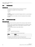
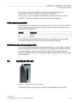
Figure 3-1
Slot for the SD card (yellow frame)
You will find the SD cards supported by the TIM in the appendix SD cards (Page 303).

