UTMC OTU/MOVA Handbook
667/HB/31601/000
Page 47
Issue 5
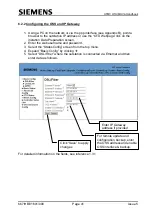
6.3.5 Modifying and Saving the I/O Bit Mapping for Freestanding OTU
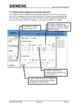
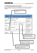
6.3.6 SCOOT Detector Mapping via OTU I/O Card
As for semi-integral OTU - see section 6.2.6.
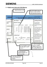
2. All reply bits,
except SCOOT,
should be inverted.
4. Use “Submit” to save
the changes on each
screen.
5. Use “Save to File” to
activate and store all
changes.
1. Select the Site to edit.
NB: UTC offsets start at 1.
Values of 0 are used for
locally generated signals.
3. Control and reply bit
mapping must match the
controller interface wiring.
Numbers start at 1 not 0.


