UTMC OTU/MOVA Handbook
667/HB/31601/000
Page 27
Issue 5
Connect the modem serial port to 9-Way ‘D’ Type on ribbon cable connected to Plug
PL2 on the CPU card.
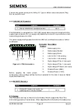
4.2.3 120/230V AC Operation
Set up 120/230V AC operation selection
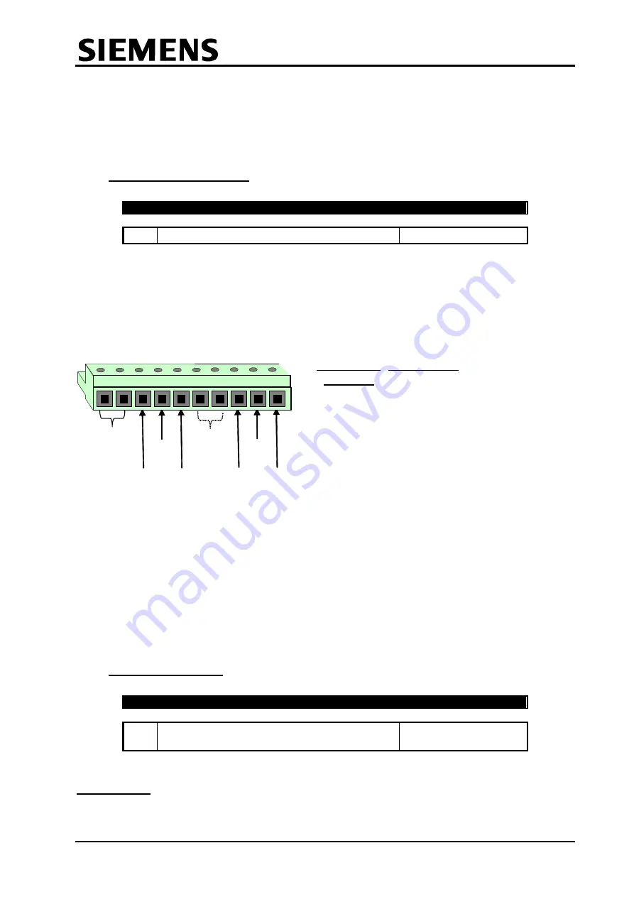
If the Outstation is connected to a 110V/120V supply then a wire link is required on the
supply input connector (PL1 on supply unit) between pins 4 and 5 to provide the correct
mains timing reference for ZXO.
The power supply itself operates from 85V to 265V AC and therefore needs no further
modification.
HIV
Return
HIV No.
2
HIV No.
1
Neutral
5
6
7
8
9
10
Link for
110V
1
2
3
4
EXT
Power
Earth
Live
Figure 4.3
-
PSU Connectors
Before applying the mains power,
recheck the correct voltage setting has been selected for the Zero Crossover Mains’
Input (ZXO Mains I/P).
4.2.4 RAM RTC Back-Up
8
Enable RTC battery and confirm the
watchdog link is correctly installed
RTC Battery
The Processor card has a Lithium Coin Cell battery fitted to support the Real Time
Clock during periods of mains failure. When dispatched from the factory this battery has
Connector
Position
Description
1
Mains supply Live
2
Mains supply Neutral
3
Mains supply Earth
4
Link to 5 for 110V working
5
Link to 4 for 110V working
6
High voltage I/P No. 2 (not used)
7
High voltage I/P No. 1 (not used)
8
High voltage I/P Return (not used)
9
External Power (GND)
10
External Power (13.8V)


