UTMC OTU/MOVA Handbook
667/HB/31601/000
Page 32
Issue 5
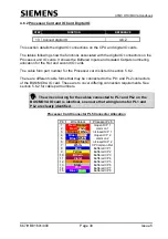
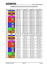
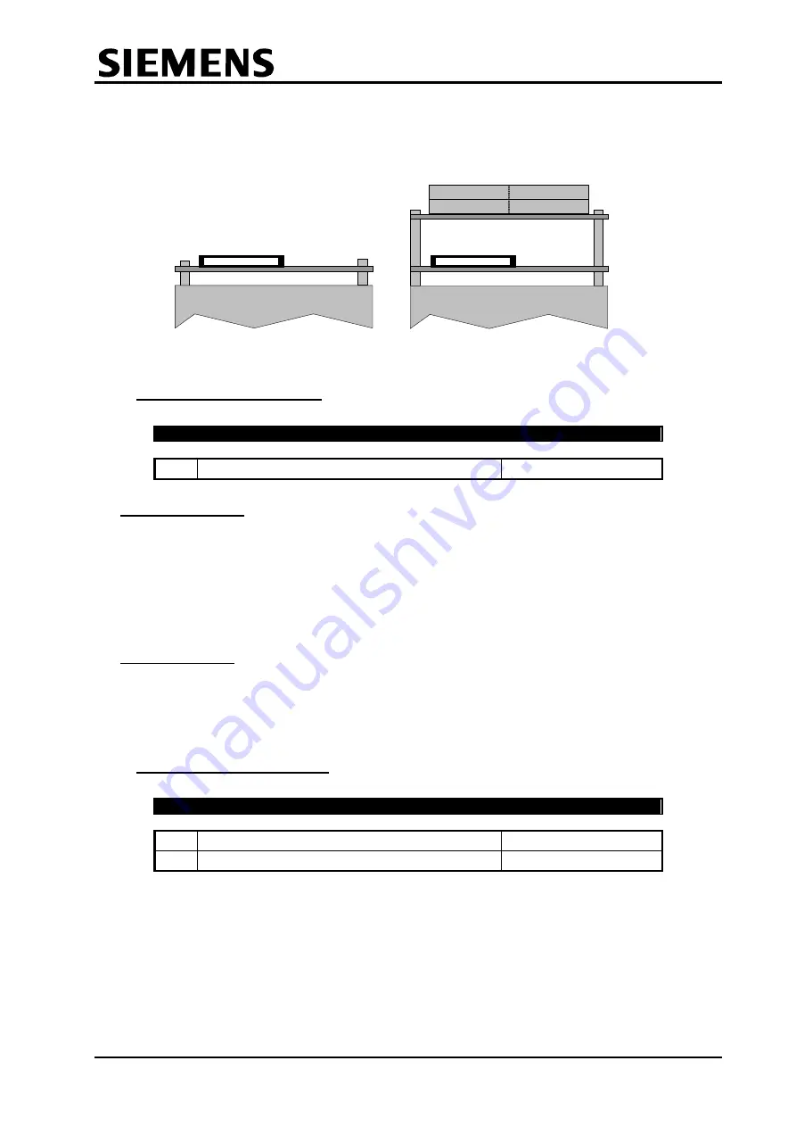
CPU card only
CPU card + 1 IO card
Pin 50
Pin 50
PL1
PL2
Pin 1
Pin 1
1st
IO
Card
CPU
Card
PL5
PL5
Viewed from Rear
4.6.3 Post Installation Checks
Complete post installation check
(a) Routing of cables
Signals for the following groups may be bunched together but must not be grouped to
other cables or other cabinet signals to reduce the occurrence of extraneous signals
causing interference.
Group 1 – Digital Level Signals
Group 2 – Mains Voltage Signals
(b) Earth Continuity
The EARTH CONTINUITY RESISTANCE must not exceed 0.5 on exposed metal
parts of the unit when measured with reference to the EARTHING TERMINATION
POINT of the cabinet.
4.6.4 Cable Form Identification
Identify all connectors/cable forms
Connect all connectors to the unit
The label sleeve attached to all Monitoring Cable Form Assemblies, with the specific
purpose of identifying the I/O Board and connector to which the cable form assembly is
connected, should be marked with a permanent marker pen to identify its connector ID
and board location, as follows:
For example:
‘PL1/1’ = Plug 1 – Board 1
‘PL4/3’ = Plug 4 – Board 3


