Installation
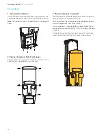
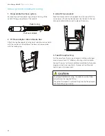
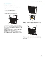
4. Disconnect front panel
There are three points to disconnect:
1. Wiring to the top, rear panel.
Squeeze the connector to disconnect.
2.
Earthing
strap.
Unscrew the nut on the metalwork with a 10mm socket.
Remove the nut and earthing strap lug from the stud.
3. Connector ‘B’ on the HMI panel.
Connector ‘B’ detaches by squeezing the connector front and
rear with your fingers and pulling down.
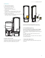
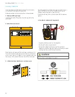
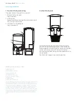
5. Remove service covers
To prepare the wiring for the VersiCharge Ultra, remove the
service hatch and cover to allow access to the internal
enclosure. Use an 8mm socket and 2.5mm hex bits.
The Service Hatch has an attached gasket. Ensure this is
carefully stored to avoid damage or accumulation of debris.
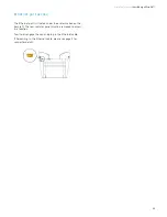
6. Pre-installation power up
The Ultra 50 is shipped with a temporary single-phase power
cable which allows the unit to be powered prior to installation.
This is attached to the M40 blanking plug. This allows for
software updates, charger configuration and/or 4G connectivity
testing.
The cable has a male IEC socket and an IEC female lead is
required to supply power.
If pre-installation power up is required, contact your supplier to
synchronize with Siemens.
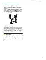
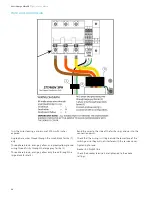
7. Remove IEC cable wiring
Remove the M40 blanking plug and IEC cable wiring from the
switch gear.
1
2
3
EXPLODED VIEW
Service
Cover
Service
Hatch
FRONT VIEW
Installation Manual
| VersiCharge Ultra 50™
19
Summary of Contents for VersiCharge Ultra 50
Page 2: ...2 ...


