31
Siemens Building Technologies
Fire Safety & Security Products
10.2008
9.3
Connecting alarm inputs
You can connect a total of 128 alarm inputs to a VIS3I-328, making a total of 256
alarms inputs for each expanded node.
You can connect Volt-free contacts from external alarm sources directly to the
alarm connector on the rear panel of the unit (see Fig. 7).
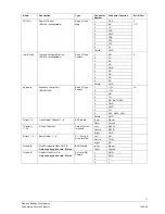
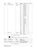
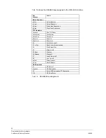
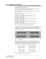
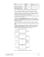
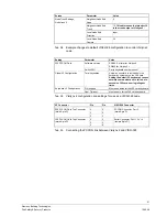
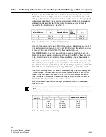
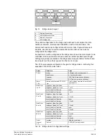
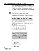
Pin connections for the alarm connector are shown in Tab. 15. A typical example of
alarm connections is:
PIN 1 to PIN 20
PIN 2 to PIN 20
PIN 3 to PIN 20
Alarm contact 1
Alarm contact 2
Alarm contact 3
Similar for alarm contacts 4 – 16
PIN 1 to PIN 21
PIN 2 to PIN 21
PIN 3 to PIN 21
Alarm contact 17
Alarm contact 18
Alarm contact 19
Similar for alarm contacts 20 – 32
PIN 1 to PIN 22
PIN 2 to PIN 22
PIN 3 to PIN 22
Alarm contact 33
Alarm contact 34
Alarm contact 35
Similar for alarm contacts 36 – 48
PIN 1 to PIN 27
PIN 2 to PIN 27
PIN 3 to PIN 27
Alarm contact 113
Alarm contact 114
Alarm contact 115
Similar for alarm contacts 116 – 128
Tab. 15
Typical alarm connections direct to alarm connector
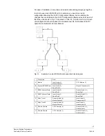
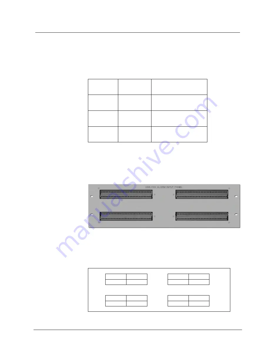
For numerous alarms a separate optional alarm panel (Type VIS3-ALARMBOX) is
available for ease of installation. The alarm panel fits into a standard 19" rack
cabinet. A 37-way to 37-way cable (Type VIS3-ALMCAB) connects the alarm panel
to the unit alarm connector.
Fig. 11
Alarm panel
All individual alarm input connections are made via pairs of terminals (one above
the other) on the alarm panel, using a pair of volt-free wires for each alarm. You
configure each input using VisiPC as a normally open (N/O) or a normally closed
(N/C) contact. The 128 alarm inputs are provided in 8 separate banks.
Bank 1
Bank 2
Bank 3
Bank 4
1–16
17–32
33–48
49–64
Common Common
Common Common
Bank 5
Bank 6
Bank 7
Bank 8
65–80
81–96 97–112
113–128
Common Common
Common Common
Tab. 16
Alarm panel – terminal identification

