41
Siemens Building Technologies
Fire Safety & Security Products
10.2008
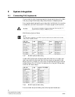
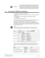
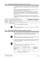
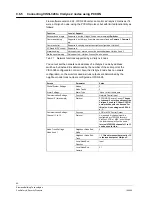
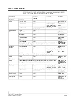
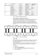
Screen Parameter
Value
Neighbour Node End,
Node
2
Neighbour Node End,
Trunk
16.
This determines that monitor 16
is the trunk output at Visilynx 2.
Local Node End,
Direction
Input
Node Trunk Settings,
Node trunk 2
Local Node End,
Camera
32
Tab. 28
Example changes to default VIS3I-328 configuration to control Visilynx 2
node
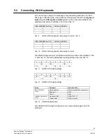
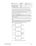
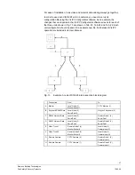
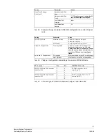
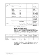
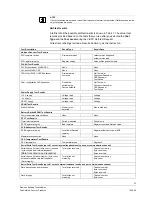
Setting Parameter
Value
Software version
SW182-5 or later for Visilynx 2
SW235 for Visilynx 2+
309 PCCON Card
Switch SW1
Set to keyboard number minus 1
Global V2 Configuration
Total keyboards
As
low as possible
, to include only the
keyboard number set on the 309 card.
Setting the default 32 keyboards causes
network communications to fail, due to
excessive 309 card user login/logout
times.
PIN support
Must be
enabled
for the 309 card keyboard
Keyboard V2 Configuration
User Timeout
Must be
zero
for the 309 card keyboard
Tab. 29
Visilynx 2 configuration and settings for use as a VIS3I-328 node
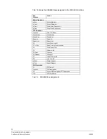
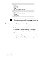
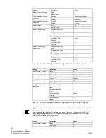
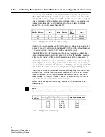
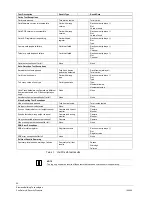
V2 Connector
Pin
Pin
VIS3I-328 Connector
2 3
3 2
309 PCCON Card Top Connector
(male 9-pin D)
5 5
PCCON Connector, Port 2
(male 9-pin D)
2 2
3 3
309 PCCON Card Top Connector
(male 9-pin D)
5 6
Serial Connector, Port 1, 3 or 4
(female 9-pin D)
Tab. 30
Connecting the PCCON link between Visilynx 2 and VIS3I-328

